
Control device and smart illumination device and system

A technology for control devices and lighting equipment, applied in lighting devices, energy-saving control technology, lamp circuit layout, etc., can solve the problems of rigid control, inability to share data with each other, and inconvenient interaction of control and data, etc., so as to solve the inconvenience of control Effect

Inactive Publication Date: 2018-07-20
SHANGHAI SANSI ELECTRONICS ENG +2
View PDF13 Cites 7 Cited by
  • Summary
  • Abstract
  • Description
  • Claims
  • Application Information

AI Technical Summary

Problems solved by technology

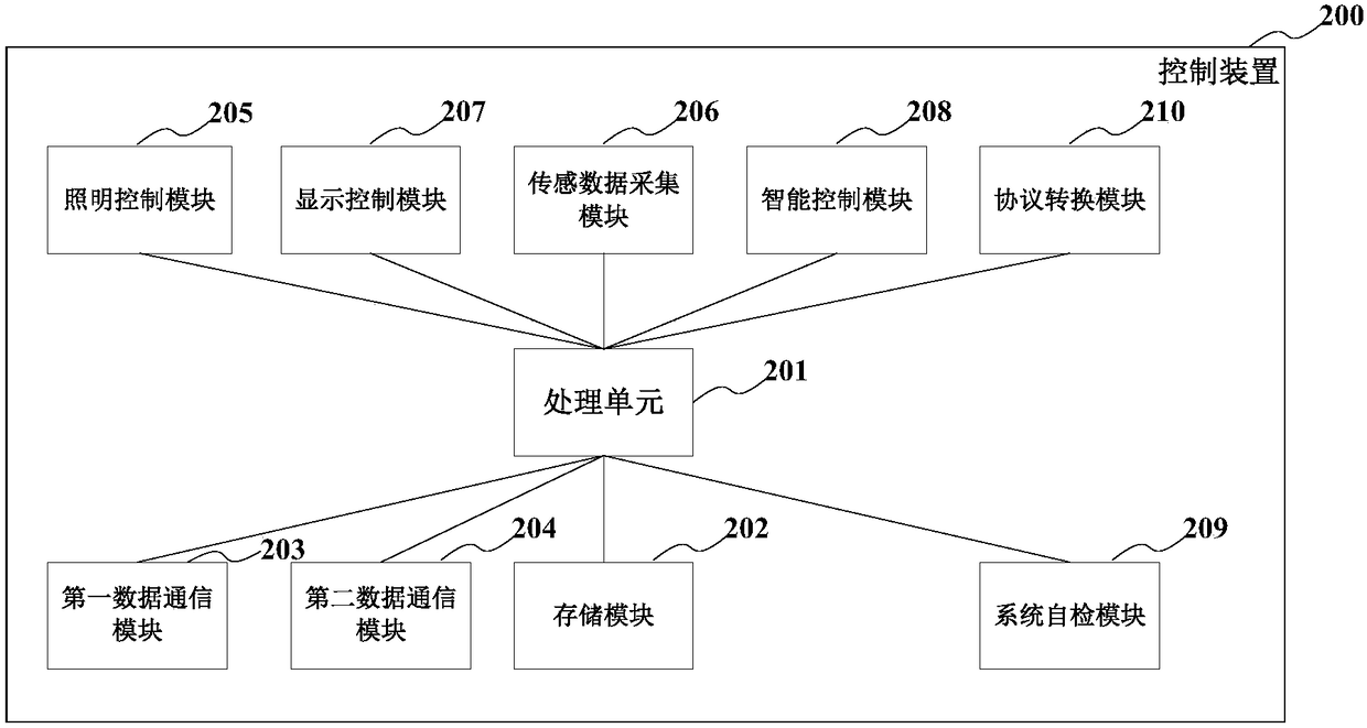
[0002] With the acceleration of urbanization, the demand for urban public lighting facilities is increasing. In particular, smart street lights have appeared on urban roads. The current smart lighting equipment is relatively rigid in terms of control, which means that manufacturers Centralized production of a batch of the same smart lighting equipment is then installed on urban roads. Although the existing smart lighting equipment has modules such as displays, cameras, and sensors, it cannot centrally control these modules. Moreover, each smart lighting device is independent and cannot share data with each other. For the construction of smart cloud cities, there are certain disadvantages
And, in the existing smart lighting equipment, the controllers of each module are independent of each other, which is inconvenient in terms of control and data interaction

Method used


Image

  • Control device and smart illumination device and system
  • Control device and smart illumination device and system
  • Control device and smart illumination device and system

Examples


Embodiment Construction

[0024] Embodiments of the present invention are described below through specific examples, and those skilled in the art can easily understand other advantages and effects of the present invention from the content disclosed in this specification. The present invention can also be implemented or applied through other different specific implementation modes, and various modifications or changes can be made to the details in this specification based on different viewpoints and applications without departing from the spirit of the present invention. It should be noted that, in the case of no conflict, the following embodiments and features in the embodiments can be combined with each other.

[0025] It should be noted that the diagrams provided in the following embodiments are only schematically illustrating the basic ideas of the present invention, and only the components related to the present invention are shown in the diagrams rather than the number, shape and shape of the compo...


PUM


Abstract

The invention provides a control device and a smart illumination device and system. The control device is in communication connection to one or multiple electronic equipment of the smart illuminationdevice, and the control device is in network communication with cloud equipment; via the control device, cloud equipment realizes remote control for the electronic equipment of the smart illuminationdevice, and / or the control device controls the electronic equipment of the smart illumination device locally according to a pre-stored control instruction; and the control device of different smart illumination devices communicate with one another to realize remote and / or local management of the smart illumination device. The problem that the smart illumination device is inconvenient to control inthe prior art is solved.

Description

technical field [0001] The invention relates to the technical field of intelligent lighting equipment, in particular to a control device, intelligent lighting equipment and an intelligent lighting system. Background technique [0002] With the acceleration of urbanization, the demand for urban public lighting facilities is increasing. In particular, smart street lights have appeared on urban roads. The current smart lighting equipment is relatively rigid in terms of control, which means that manufacturers Centralized production of a batch of the same smart lighting equipment is then installed on urban roads. Although the existing smart lighting equipment has modules such as displays, cameras, and sensors, it cannot centrally control these modules. Moreover, each smart lighting device is independent and cannot share data with each other, which has certain disadvantages for building a smart cloud city. And, in the existing smart lighting equipment, the controllers of each mod...

Claims


Application Information

Patent Timeline
IPC IPC(8): H05B37/02
CPCH05B47/105H05B47/19Y02B20/40
Inventor 姜玉稀李应启唐德刘海斌
Owner SHANGHAI SANSI ELECTRONICS ENG
Learn More