
Experiential helmet simulation demonstration mechanism

A demonstration mechanism and safety helmet technology, which is applied in the field of mechanical teaching equipment, can solve the problems of casualties, large pulling range, and high falling height of heavy blocks, and achieve the effects of avoiding safety accidents, avoiding collapse, and facilitating disassembly and assembly

Inactive Publication Date: 2018-07-20
DONGGUAN UNIV OF TECH
View PDF0 Cites 0 Cited by
  • Summary
  • Abstract
  • Description
  • Claims
  • Application Information

AI Technical Summary

Problems solved by technology

[0002] With the advancement of mechanization, the number of students in the mechanical field is increasing. Due to the various uncertain risk factors in the factory, most schools will teach students about safety. In order to improve the teaching effect, it is best to experience safety equipment by yourself. Therefore, there have been some teaching and demonstration devices, among which the helmet demonstration mechanism is the most common teaching and demonstration mechanism. Most of the existing teaching and demonstration mechanisms are very simple. A certain height turns down on the student's helmet wearing the helmet through the free fall movement, so that the students can feel the effect of the helmet, and then wear the helmet. Manually pulling the rope, it is easy to cause the height of the weight to fall too high due to excessive pulling range, causing casualties and accidents

Method used


Image

  • Experiential helmet simulation demonstration mechanism
  • Experiential helmet simulation demonstration mechanism
  • Experiential helmet simulation demonstration mechanism

Examples


Embodiment Construction

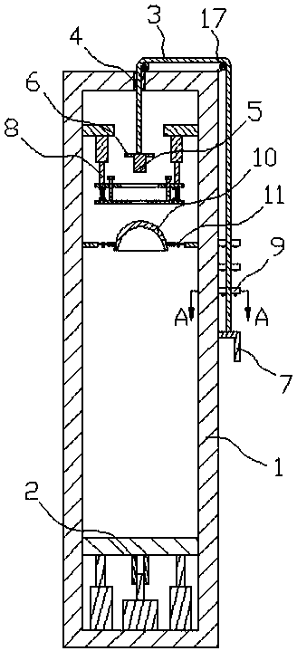
[0028] In order to enable those skilled in the art to better understand the technical solution of the present invention, the present invention will be described in detail below in conjunction with the accompanying drawings. The description in this part is only exemplary and explanatory, and should not have any limiting effect on the protection scope of the present invention. .

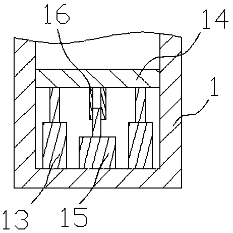
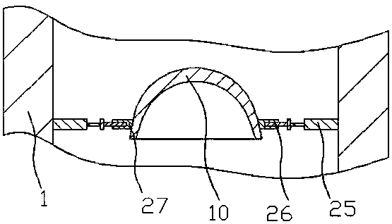
[0029] Such as Figure 1-Figure 7 As shown, the specific structure of the present invention is: an experiential safety helmet simulation demonstration mechanism, including a cabinet body 1 and a stay rope 3 running through the upper part of the cabinet body, and the stay rope is located at one end of the cabinet body 1 and is connected with a weight 5 , the other end is perpendicular to the outside of the cabinet 1 through the pulley 17 and is connected with a pull handle 7, the outside of the weight 4 is provided with a weight limit matching block 6, and the cabinet 1 is provided with a The weight li...


PUM


Abstract

The invention relates to an experiential helmet simulation demonstration mechanism. The experiential helmet simulation demonstration mechanism includes a cabinet and a dragrope which penetrates through the upper portion of the cabinet; a weight is connected to the end, located at the cabinet, of the dragrope; the other end of the dragrope is perpendicular to the outer side of the cabinet through apulley and is connected with a pull handle; a weight limit matched block is arranged at the outer side of the weight, a weight limit device matched with the weight limit matched block is arranged inthe cabinet and includes weight limit mounting blocks arranged in the cabinet, weight limit adjusting air cylinders are arranged below the weight limit mounting blocks, weight limit blocks are connected to the lower portions of the weight limit adjusting air cylinders, and first matched holes of which the diameters are larger than the width of the weight and smaller than the width of the weight limit mounting blocks are formed in the middles of the weight limit blocks. According to the experiential helmet simulation demonstration mechanism, the weight limit device is arranged on the upper portion of the cabinet, through the weight limit blocks and the weight limit matched block which is arranged on the side face of the weight, an overlarge falling range can be avoided, and the situation isfurther avoided that experiencers are injured due to caused accidents, so that the safety of teaching is ensured.

Description

technical field [0001] The invention relates to the field of mechanical teaching equipment, in particular to an experiential safety helmet simulation demonstration mechanism. Background technique [0002] With the advancement of mechanization, the number of students in the mechanical field is increasing. Due to the various uncertain risk factors in the factory, most schools will teach students about safety. In order to improve the teaching effect, it is best to experience safety equipment by yourself. Therefore, there have been some teaching and demonstration devices, among which the helmet demonstration mechanism is the most common teaching and demonstration mechanism. Most of the existing teaching and demonstration mechanisms are very simple. A certain height turns down on the student's helmet wearing the helmet through the free fall movement, so that the students can feel the effect of the helmet, and then wear the helmet. Manually pulling the stay rope is prone to exces...

Claims


Application Information

Patent Timeline
Patent Type & Authority Applications(China)
IPC IPC(8): G09B25/00
CPCG09B25/00
Inventor 黄辉宇罗剑英
Owner DONGGUAN UNIV OF TECH
Learn More