
Bolt looseness detection and alarm device for rail joint connecting component

A technology of bolt loosening and alarm device, applied in the field of automatic alarm device and bolt loosening detection, can solve the problems of high false detection rate, train climbing accident, heavy workload, etc., and achieve the effect of low false detection rate

Active Publication Date: 2018-07-20
EAST CHINA JIAOTONG UNIVERSITY
View PDF9 Cites 14 Cited by
  • Summary
  • Abstract
  • Description
  • Claims
  • Application Information

AI Technical Summary

Problems solved by technology

As the wheels that guide the rolling stock, the rails are subjected to tremendous pressure on the wheels, and as the vehicles pass by, the corresponding rails will also vibrate. When the rails vibrate, the connecting parts of the rail joints will also vibrate accordingly. The bolts connecting the parts loosen, causing the rail joints to shift, and in severe cases, it will cause a train climbing accident
[0003] In the prior art, the railway workers found the loose bolts of the rail joint joint parts from the abnormal sound after hitting the rails with a hammer, that is, when the railway workers hit the rails with a hammer, the loosening of the bolts changed the structure of the subtle parts of the object, then According to the different timbres of their sounds, it can be judged whether the bolts of the rail joint connecting parts are loose. However, this detection method not only has a large workload and a high false detection rate, but also needs to frequently detect the looseness of each rail joint connecting part. bolt

Method used


Image

  • Bolt looseness detection and alarm device for rail joint connecting component
  • Bolt looseness detection and alarm device for rail joint connecting component
  • Bolt looseness detection and alarm device for rail joint connecting component

Examples


Embodiment Construction

[0042] The present invention will be described in further detail below in conjunction with the embodiments and with reference to the accompanying drawings.

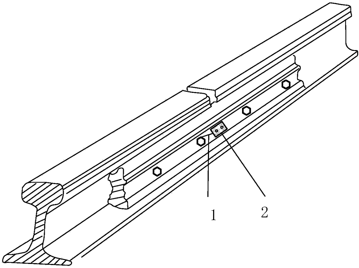
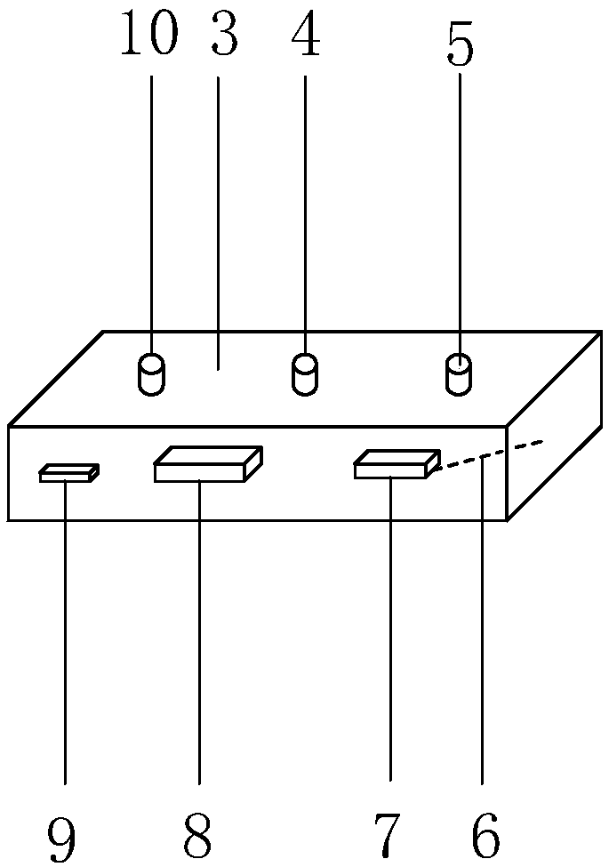
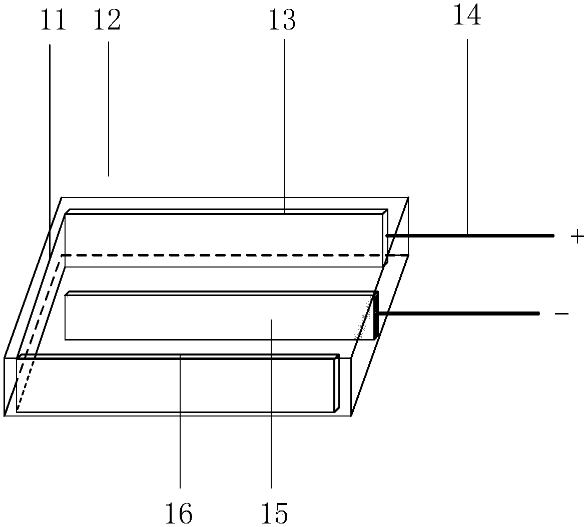
[0043] see Figures 1 to 7 , shows the bolt looseness detection and alarm device for rail joint joint parts in the first embodiment of the present invention, including a steel wire 1 and a bolt looseness detector 2 .

[0044] Such as figure 1 As shown, one end of the steel wire 1 is welded on the head of the bolt of the rail joint joint part, and the other end is connected with the negative lead 6 of the bolt loosening detector 2, and the bolt loosening detector 2 is installed on the splint on the side away from the rail Surface, and between two adjacent through holes on the splint, used to detect the loosening of bolts and remind railway workers that the bolts are loosened. Together, when the bolt is loose, it will generate a pulling force on the steel wire 1, and the pulling force of the steel wire 1 will cause the ou...


PUM


Abstract

The invention relates to a bolt looseness detection and alarm device for a rail joint connecting component, which comprises a steel wire and a bolt looseness detector, wherein one end of the steel wire is welded at the head of a bolt of the rail joint connecting component, the other end is connected with a negative electrode wire of the bolt looseness detector, the bolt looseness detector is installed at the surface, which is away from the rail, of a clamping plate, located between two adjacent through holes on the clamping plate and used for detecting the looseness of the bolt and reminding railway workers of the looseness of the bolt, the steel wire connects the head of the bolt of the rail joint connecting component and the bolt looseness detector together, a pulling force is generatedfor the steel wire when the bolt gets loose, the pulling force of the steel wire enables an output value of a looseness sensor of the bolt looseness detector to be changed, and a main control board judges a loosened bolt according to a variation value of the looseness sensor and turns on an indicator lamp at the same time to give an alarm to the railway workers.

Description

technical field [0001] The invention relates to a bolt looseness detection and automatic alarm device on rails, in particular to a bolt looseness detection and alarm device for rail joint joint parts. Background technique [0002] The rail joint refers to the structure that the rails on the track are connected by splints and bolts so that the train can run continuously. The wheel-rail dynamic effect at the rail joint is large, and the maintenance and repair workload is large, which is one of the weak links of the track structure. As the wheels that guide the rolling stock, the rails are subjected to tremendous pressure on the wheels, and as the vehicles pass by, the corresponding rails will also vibrate. When the rails vibrate, the connecting parts of the rail joints will also vibrate accordingly. The bolts connecting the parts loosen, causing the rail joint to shift, and in severe cases, it will cause the train to climb the rail accident. [0003] In the prior art, the ra...

Claims


Application Information

Patent Timeline
Patent Type & Authority Applications(China)
IPC IPC(8): G01M13/00G01L5/24B61K9/08
CPCB61K9/08G01L5/24G01M13/00
Inventor 姜小刚胡军王海阳刘燕德孙旭东
Owner EAST CHINA JIAOTONG UNIVERSITY
Learn More