Wheel type robot chassis

A wheeled robot and chassis technology, which is applied in the direction of instruments, motor vehicles, vehicle springs, etc., can solve the problems of difficult to achieve precise control, inability to realize in-situ steering, lack of flexibility, etc., and achieve the effect of strong obstacle surmounting ability

Pending Publication Date: 2018-07-20
长沙万为机器人有限公司
View PDF0 Cites 4 Cited by
  • Summary
  • Abstract
  • Description
  • Claims
  • Application Information

AI Technical Summary

Problems solved by technology

[0003] Some wheeled robot chassis adopt the structure of two driving wheels in the front and one or two universal wheels in the back. This kind of chassis is generally arranged in a square shape. Although it has a certain ability to overcome obstacles, its stability is poor and it cannot Steering in place, lack of flexibility
[0004] There are also some robots whose chassis adopt four-wheel drive or crawler-type drive wheels, which are superior in heavy load and obstacle surmounting, but the wheels slip during the turning process, resulting in unrealistic wheel speed feedback and large errors, which are difficult to do. to precise control
[0005] Moreover, the robot chassis of the above structure is generally not equipped with a collision detection device. Even if a collision detection device is configured, one or several micro touch switches are used to detect a small area in a certain direction alone, which makes it difficult to achieve full coverage layout and complex structure. , and there is a detection blind spot

Method used


Image

  • Wheel type robot chassis
  • Wheel type robot chassis
  • Wheel type robot chassis

Examples


Embodiment 1

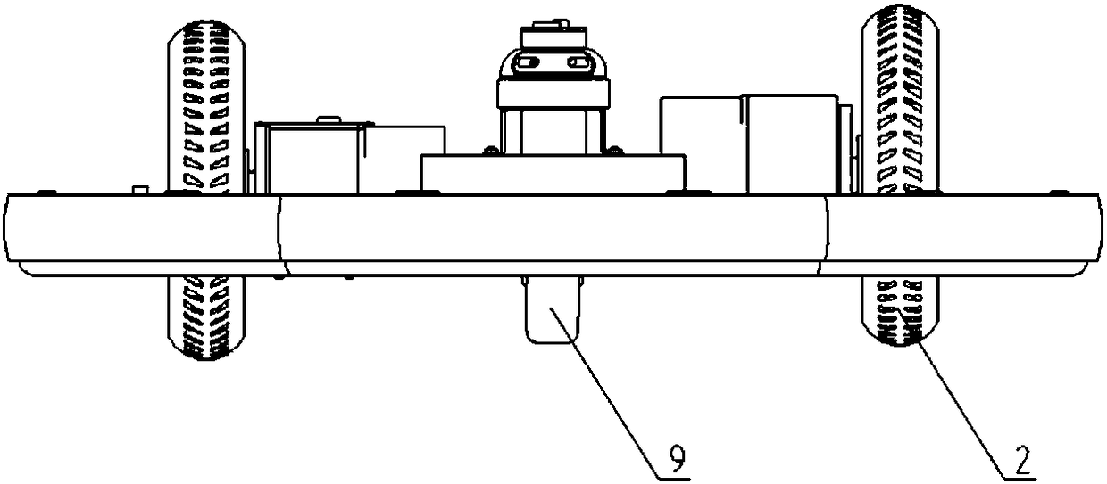
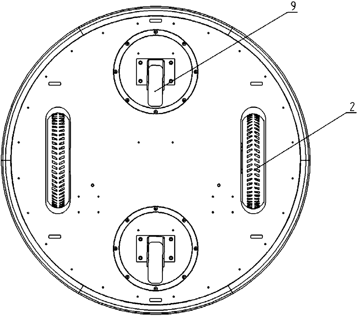
[0036] Embodiment one, such as figure 1 , figure 2 As shown, the wheeled robot chassis disclosed in this embodiment includes a circular base plate 1, a driving wheel 2, a universal wheel mounting seat 3, an elastic suspension device 4, a collision detection device 5, a chassis controller 6, and a laser radar 7 , infrared ranging sensor 8, universal wheel 9.

[0037] combine Figure 1 to Figure 4 It can be seen that two universal wheels 9, front and rear, and two driving wheels 2, left and right, are connected to the circular bottom plate 1, and the two universal wheels 9 and the two driving wheels 2 are arranged in a rhombus shape.

[0038] from figure 1 It can be seen that the universal wheel mounting seat 3, the elastic suspension device 4, the chassis controller 6 and the infrared ranging sensor 8 are all installed on the upper side of the circular base plate 1, and the laser radar 7 is installed on the front universal wheel through a bracket. Seat 3. The chassis cont...

Embodiment 2

[0052] Embodiment 2. The difference between this embodiment and Embodiment 1 is that the elastic suspension device is different, and other structures are the same as Embodiment 1.

[0053] The elastic suspension device of this embodiment adopts Figure 15 to Figure 18 Structure.

[0054] Figure 15 to Figure 18 The elastic suspension shown with the Figure 7 to Figure 10 The difference of the shown elastic suspension device is that the self-adaptive elastic adjustment member adopts extension spring LH. Thus the corresponding structural changes are mainly the layout and installation of the extension springs.

[0055] From Figure 15 to Figure 18 It can be seen that the extension spring LH is arranged parallel to the driving wheel 2 along the front-rear direction, the extension spring mounting seat LHZ at one end is connected to the upper side of the two bracket plates 43 , and the other extension spring mounting seat LHZ is connected to the installation base plate 41 . One...


PUM


Abstract

The invention discloses a wheel type robot chassis. The wheel type robot chassis comprises a round base plate, front and back universal wheels and left and right driving wheels, wherein the front andback universal wheels and the left and right driving wheels are connected to the round base, the universal wheels and the driving wheels are arranged in a rhombus shape, and the driving wheels are connected with a driving device. The driving wheels and the driving device thereof are connected to the round base plate through an elastic hanging device, the round base plate is connected with a collision detection device, and the collision detection device comprises a plurality of air pressure testing modules which are evenly distributed on the peripheral edge of the round base plate, and the airpressure testing modules are used for outputting collision signals when the air pressure increases. When the road surface changes, the elastic hanging device has an adaptive function, so that the driving wheels are always in contact with the ground and always has the driving ability, so that the wheel type robot is suitable for both flat environment and uneven environment, and the obstacle climbing ability is high. The collision detection device can detect the external collision force of the robot through the changes of air pressure reflected by the air pressure testing modules at different positions and realize the all-round anti-collision.

Description

technical field [0001] The invention relates to a wheeled robot, in particular to a wheeled robot chassis. Background technique [0002] At present, the chassis structure of wheeled robots is generally a diamond-shaped arrangement of front and rear universal wheels and left and right driving wheels. Steering is achieved through differential speed, which has the advantages of simple control and flexible actions, but it can only be applied to a completely flat environment. [0003] Some wheeled robot chassis adopt the structure of two driving wheels in the front and one or two universal wheels in the back. This kind of chassis is generally arranged in a square shape. Although it has a certain ability to overcome obstacles, its stability is poor and it cannot Steering in situ, lack of flexibility. [0004] There are also some robots whose chassis adopt four-wheel drive or crawler-type drive wheels, which are superior in heavy load and obstacle surmounting, but the wheels slip ...

Claims


Application Information

Patent Timeline
IPC IPC(8): B62D61/04B60G11/16G05D1/02
CPCG05D1/0231B62D61/04B60G11/16B60G2202/12
Inventor 蔡佳豪李金波冯泽根
Owner 长沙万为机器人有限公司
Why Eureka
Try Eureka