Medical equipment clamping device

A medical device and robotic arm technology, applied in the field of medical device gripping devices, can solve problems such as easy shaking, damage to the surface of medical devices, and low stability, and achieve the effect of not being easy to shake, easy to adjust, and good stability

Inactive Publication Date: 2018-07-20
GUILIN JIAHONG ELECTRONICS TECH CO LTD
View PDF1 Cites 4 Cited by
  • Summary
  • Abstract
  • Description
  • Claims
  • Application Information

AI Technical Summary

Problems solved by technology

[0002] The medical device clamping device is a device for clamping medical devices. It is a device for quickly grasping medical devices. It can solve the inconvenience of taking special medical devices and does not need to change gloves constantly. The clamping claws on the device clamp the medical instruments, but in the process of clamping the medical instruments, the clamping is difficult and cannot be applied to medical instruments of various sizes. When clamping smaller medical instruments , the clamped medical device is prone to shaking inside the clamping jaw
[0003] The Chinese patent with the authorized announcement number 201711047087.8 discloses a medical device clamping device, which is suitable for clamping medical devices of different sizes. The patent adopts bevel gear transmission, and the chuck initially clamps the medical device. The medical device is tightly fitted, but in actual use, when the adjustment is made through the transmission and rotation of the bevel gear, it is impossible to grasp the pressure generated by the deformation of the hollow cavity on the medical device. Damage occurs due to excessive pressure, the rotation of the bevel gear is only one-sided adjustment of the clamping arm, and the stability is not high

Method used


Image

  • Medical equipment clamping device
  • Medical equipment clamping device
  • Medical equipment clamping device

Examples


Embodiment Construction

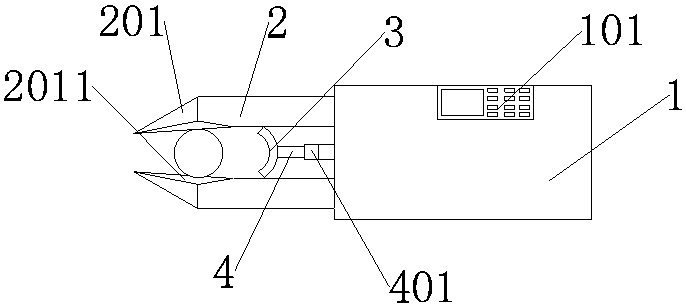
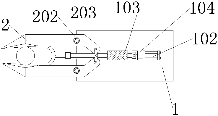
[0030] A medical device gripping device name, such as figure 1 As shown, the frame 1, the mechanical arm 2, and the mechanical arm 2 are movably installed on the left side of the frame 1. There are two mechanical arms 2. The outer surface of the frame 1 is provided with a controller 101, and the controller 101 is fixedly installed. On the frame 1, the inside of the frame 1 is provided with a sliding guide block 103, and the sliding guide block 103 is slidably connected to the push rod 4. The sliding guide block 103 ensures the stability of the push rod 4 movement, avoids shaking from side to side, and ensures Clamping stability, the interior of the frame 1 is provided with a hydraulic cylinder 102 and a motor 104, the hydraulic cylinder 102 and the motor 104 are electrically connected to the controller 101, and the movement of the hydraulic cylinder 102 and the motor 104 can be adjusted by controlling the controller 101 .

[0031] In the example, such as figure 1 As shown, t...


PUM


Abstract

The invention discloses a medical equipment clamping device and belongs to the field of the medical equipment. According to the technical scheme, the medical equipment clamping device is characterizedby comprising a frame, mechanical arms, an arc-shaped positioning block and a push rod; a controller is arranged on the outer surface of the frame, the mechanical arms are movably arranged on the left side of the frame, and the arc-shaped positioning block is arranged in the mechanical arms; the push rod is movably connected to the arc-shaped positioning block, a clamping claw is arranged at theleft end of each mechanical arm, and the clamping claws are welded on the mechanical arms; the outer surface of each clamping claw is sleeved with a rubber pad, a pressure detector is arranged in themiddle of the push rod and is capable of detecting the pressure on medical equipment in real time and avoiding the situation that the surface of the medical equipment is damaged due to excessive clamping pressure when the clamping pressure is excessive, the rubber pads and the positioning block are concentric, and the medical equipment can be clamped in the horizontal and vertical directions whenthe medical equipment is clamped by the mechanical arms; and it is guaranteed that the clamping portion of the medical equipment is not easy to waggle, and the stability is good.

Description

technical field [0001] The invention relates to the related technical field of medical instruments, in particular to a medical instrument clamping device. Background technique [0002] The medical device clamping device is a device for clamping medical devices. It is a device for quickly grasping medical devices. It can solve the inconvenience of taking special medical devices and does not need to change gloves constantly. The clamping claws on the device clamp the medical instruments, but in the process of clamping the medical instruments, the clamping is difficult and cannot be applied to medical instruments of various sizes. When clamping smaller medical instruments , the clamped medical device is prone to shaking inside the clamping claw. [0003] The Chinese patent with the authorized announcement number 201711047087.8 discloses a medical device clamping device, which is suitable for clamping medical devices of different sizes. The patent adopts bevel gear transmission...

Claims


Application Information

Patent Timeline
IPC IPC(8): B25B5/00B25B5/06B25B5/16
CPCB25B5/00B25B5/06B25B5/16B25B5/163
Inventor 黄永恒
Owner GUILIN JIAHONG ELECTRONICS TECH CO LTD
Why Eureka
Try Eureka