Lighting system

A technology for lighting systems and LED modules, applied in the field of lighting systems, can solve the problems of becoming more expensive and making the manufacturing process more difficult

Active Publication Date: 2018-07-17
克里斯蒂安恩格尔曼
View PDF9 Cites 0 Cited by
  • Summary
  • Abstract
  • Description
  • Claims
  • Application Information

AI Technical Summary

Problems solved by technology

The disadvantage here is that a special base is required to accommodate the LED modules, which makes the manufacturing process difficult and expensive

Method used


Image

  • Lighting system
  • Lighting system
  • Lighting system

Examples


Embodiment Construction

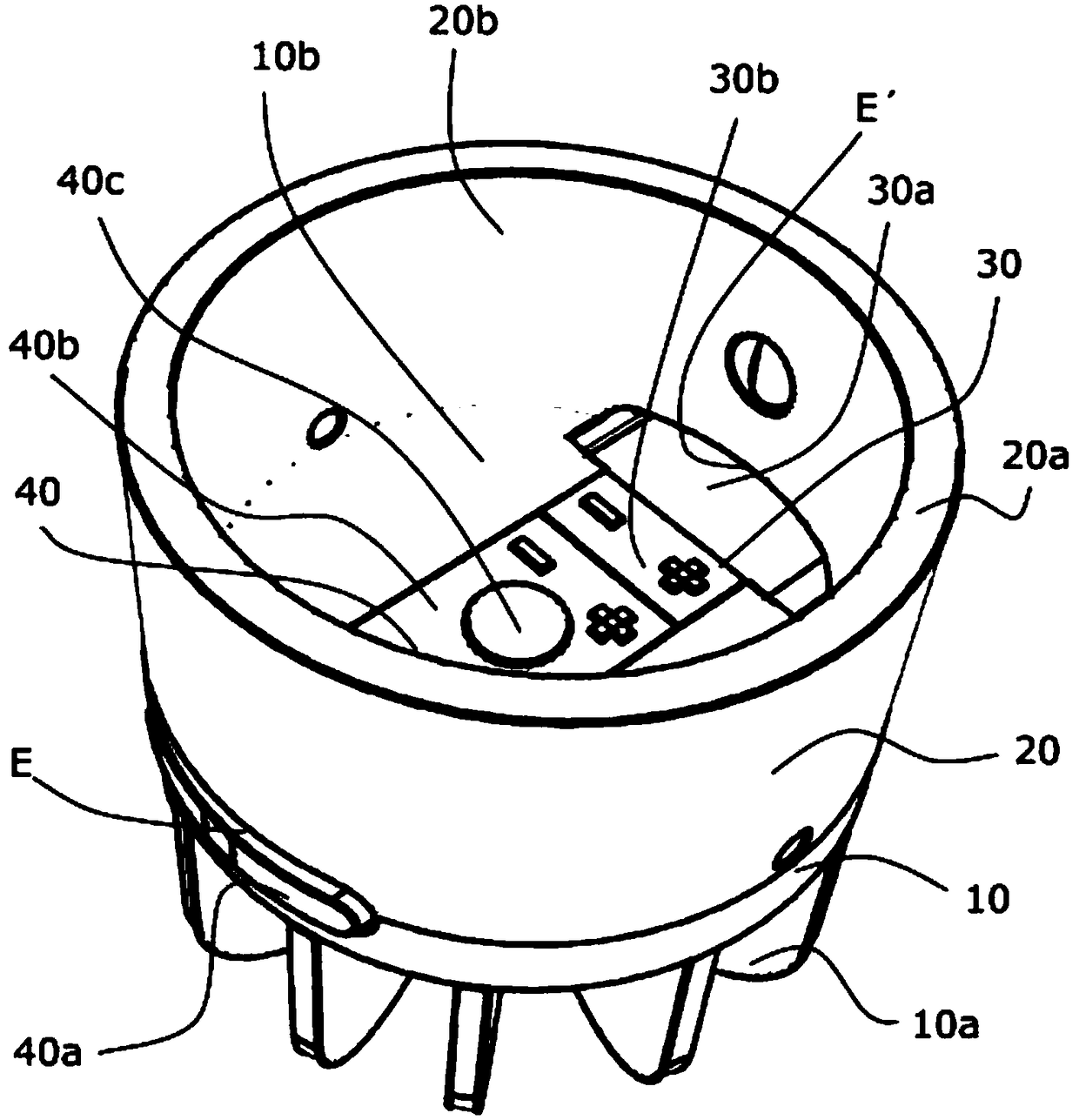
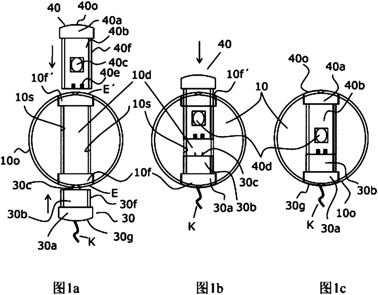
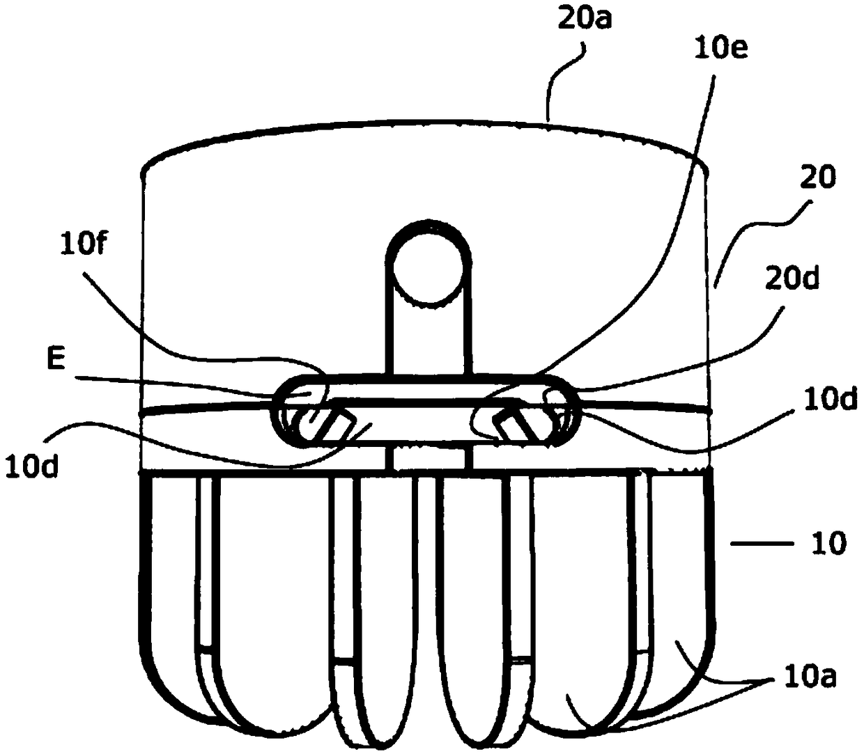
[0024] figure 1 A first possible embodiment of the lighting system according to the invention in the form of a luminous body is shown. The illuminant has a heat sink 10 and an upper part 20 fastened thereto. The heat sink 10 has on its upper side 10 b a recess 10 d into which the LED module 40 and the power supply module 30 can be inserted. The heat sink 10 and the component 20 together form lateral push-in openings E and E', into which the LED module 40 and the power supply module 30 can be pushed into from one side, so as to enter the recesses of the heat sink 10. The heat sink 10 has cooling fins 10 a on its underside. In the pushed-in state, the two modules 30 , 40 are flush with the outer wall 10 o of the heat sink 10 and the upper part 20 . The upper part 20 has a cylindrical wall 10 b with an end side 20 a. The upper part 20 can be connected to the heat sink 10 by means of a plug connection and possibly a locking connection. However, it is also possible for the upp...


PUM


Abstract

The invention relates to a lighting system, in particular in the form of a light, comprising at least one heat sink (10, 100), the heat sink (10, 100) comprises at least one first recess (10d, 100p),in particular in the form of a groove, which forms a first module receptacle for at least one LED module (40, 400). The at least one LED module (40, 400) is in the recess or can be introduced into therecess (10d, 100p), in particular, it can be pushed or slid. The first recess (10d, 100p) comprises a base wall and delimiting lateral walls (10s, 100s), and the LED module (40, 400) in the recess (10d, 100p) can be pressurised or is pressurised by at least one of the lateral walls (10s) or one part (100) which can be locked or can be fixed to the heat sink towards the base wall.

Description

technical field [0001] The invention relates to a lighting system, in particular in the form of a luminous body, which has at least one cooling body (10, 100). Background technique [0002] The use of LED modules in lighting systems is known, for example, from EP 1 590 996 B1, where a base, into which the LED modules can be inserted, is fastened to a cooling body. The disadvantage here is that a special base is required to accommodate the LED modules, which complicates and costs the manufacturing process. [0003] Similar lighting systems are known from EP 2719938 A1, US 2010 / 0025721 A1, DE 20 2008 011 979 U1 and US 2011 / 0176308 A1. A disadvantage in these systems is that the LED modules are supplied with electrical energy by means of complicated conductor rails, contact elements, etc. Contents of the invention [0004] It is an object of the present invention to provide a lighting system in which the LED modules used can be easily replaced and, moreover, can be powered ...

Claims


Application Information

Patent Timeline
Patent Type & Authority Applications(China)
IPC IPC(8): F21V19/00F21V29/503
CPCF21V19/003F21V19/0045F21V29/503F21V29/773F21Y2115/10F21V23/002F21V23/06
Inventor 克里斯蒂安·恩格尔曼
Owner 克里斯蒂安恩格尔曼
Why Eureka
Try Eureka