Injector assembly with thermal protection sleeve

A technology for thermal protection and injectors, applied to fuel injection devices, engine components, machines/engines, etc., can solve problems such as damage to liquid injectors

Active Publication Date: 2021-02-19
ROBERT BOSCH GMBH
View PDF5 Cites 0 Cited by
  • Summary
  • Abstract
  • Description
  • Claims
  • Application Information

AI Technical Summary

Problems solved by technology

But high temperatures can damage liquid injectors

Method used


Image

  • Injector assembly with thermal protection sleeve
  • Injector assembly with thermal protection sleeve
  • Injector assembly with thermal protection sleeve

Examples


Embodiment Construction

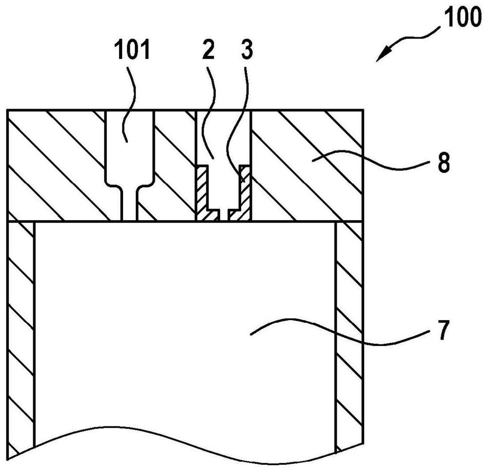
[0022] In the following, refer to Figures 1 to 3 The injector assembly 1 and the internal combustion engine 100 according to the preferred embodiment of the present invention are described in detail.

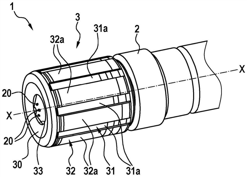
[0023] as from figure 1 and figure 2 As can be seen in the figure, the injector assembly 1 includes a liquid injector 2 , a thermal protection sleeve 3 and a gas injector 101 .

[0024] The thermal protection sleeve 3 partially surrounds the liquid injector 2, wherein, from figure 2 It can be seen that the region of the liquid injector 2 facing the combustion chamber 7 is surrounded by the thermal protection sleeve 3 .

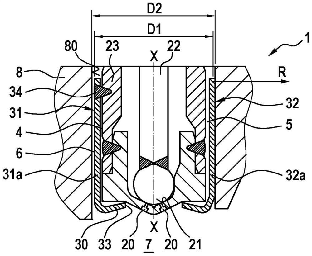
[0025] The heat protection sleeve 3 has a base region 30 , a first peripheral region 31 and a second peripheral region 32 . A cylindrical opening 33 is provided in the bottom region 30 .

[0026] from image 3 It can be seen that the spray openings 20 of the liquid injectors 2 are arranged in the region of the openings 33 of the thermal protection sleev...


PUM


Abstract

The invention relates to an injector assembly comprising: a liquid injector (2) for injecting liquid and a thermal protection sleeve (3), wherein the liquid injector (2) is at least partially arranged on the thermal protection In the sleeve (3), wherein the thermal protection sleeve (3) has a bottom area (30) with an opening (33), wherein the injection holes (20) of the liquid injector (2) are arranged in In the region of the opening (33), wherein the thermal protection sleeve (3) has a first peripheral surface region (31) and a second peripheral surface region (32), the first peripheral surface region is arranged at a first diameter (D1), the second peripheral surface area is arranged on a second diameter (D2), wherein the first diameter (D1) is smaller than the second diameter (D2), and at least the first peripheral surface area (31) and the The bottom area (30) is connected.

Description

technical field [0001] The present invention relates to an injector assembly having a thermal protection sleeve to protect the injector from excessive thermal loads. The invention also relates to an internal combustion engine having an injector for liquid fuel and an injector for gaseous fuel. Background technique [0002] Gaseous fuels such as natural gas have always been of interest in recent years due to cost advantages. Often, for reasons of extended driving distances and system redundancy, there is the possibility that the vehicle can be operated on liquid fuels in addition to gaseous fuels. In this case, internal combustion engines usually have injectors for liquid fuels in addition to gas injectors for injecting gaseous fuels. Liquid injectors are not used when running purely on gaseous fuel. In this case, fuel fills but does not flow through the injector so that heat cannot be removed from the injector by injecting liquid fuel. Since the liquid injectors are arra...

Claims


Application Information

Patent Timeline
Patent Type & Authority Patents(China)
IPC IPC(8): F02M53/04F02M61/14
CPCF02M53/046F02M61/14F02D19/027
Inventor D·普费弗勒H·登茨W·哈雷尔C·斯泰因布雷歇尔
Owner ROBERT BOSCH GMBH
Why Eureka
Try Eureka