Ocean floating body structure

A technology for offshore floating bodies and structures, applied to floating structures, hulls, hull decks, etc., can solve the problems of the hull not being able to keep up with loading, prolong the FPSO manufacturing period, and achieve the effect of shortening the construction time

Inactive Publication Date: 2018-07-17
MITSUI ENG & SHIPBUILD CO LTD
View PDF0 Cites 2 Cited by
  • Summary
  • Abstract
  • Description
  • Claims
  • Application Information

AI Technical Summary

Problems solved by technology

Therefore, if the design of the hull waits until the necessary conditions for the production equipment of each item are determined, the hull ...

Method used


Image

  • Ocean floating body structure
  • Ocean floating body structure
  • Ocean floating body structure

Examples


Embodiment Construction

[0026] The present invention will be specifically described below with reference to embodiments shown in the drawings.

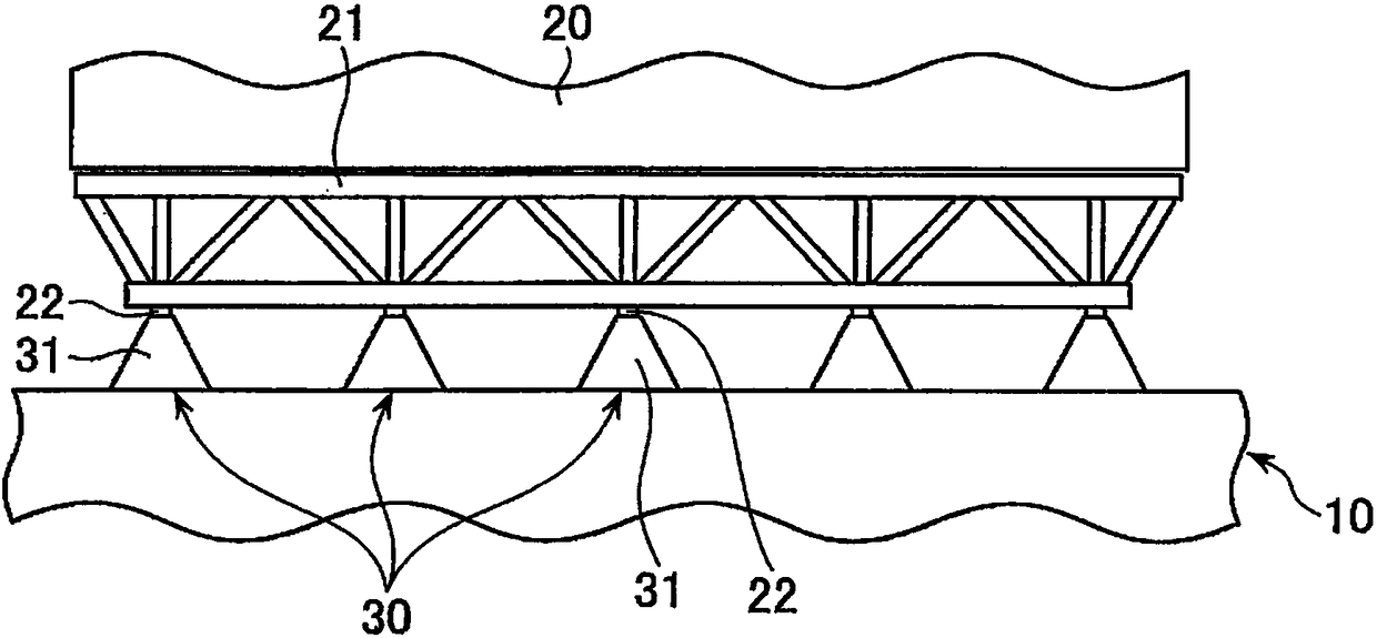
[0027] figure 1 A schematic structure on the upper deck of the FPSO applied to the first embodiment of the present invention is shown. A tank 11 is formed at the floating body 10 , and a plurality of production equipment 20 is arranged on the upper deck 12 . The production equipment 20 includes, for example, natural gas separation equipment, dehydration equipment, metering equipment, and power generation equipment, etc., and is fixed on the base 21 and installed on the bracket base 30 , wherein the bracket base 30 is installed on the upper deck 12 . The bracket base 30 is arranged in a grid shape as will be described later.

[0028] figure 2 is said to be figure 1 An enlarged view of the base 21 and the bracket seat 30 in the shown structure viewed from the side. The bracket base 30 has an inverted V-shaped main body 31 whose width becomes narrower upw...


PUM


Abstract

An ocean floating body structure, wherein production facilities can be mounted on an upper deck 12 of a floating body. The bottom surface of the upper deck 12 is provided with: transverse reinforcingmembers 40 extending in the width direction of the floating body 10; and vertical reinforcing members 41 extending in the longitudinal direction of the floating body 10. At least some of the pluralityof points on the top surface of the upper deck 12, where the transverse reinforcing members 40 and the vertical reinforcing members 41 intersect each other, are stool installation portions 43 on which stools 30 for supporting the production facilities 20 can be installed.

Description

technical field [0001] The present invention relates to an offshore floating structure as a hull portion of an FPSO (Floating Production, Storage and Offloading Unit). Background technique [0002] The FPSO is a device that can be used to produce oil or natural gas from the seabed through a riser on the ocean, store the produced crude oil in a tank, and ship it to a tanker. FPSO is different from a tanker. It not only has tanks for storage of crude oil, but also has production equipment on the upper deck. The production equipment includes various machines such as natural gas separation equipment, dehydration equipment, metering equipment, and power generation equipment. It is designed according to the characteristics of the oil well, and it is loaded after the hull is manufactured. Therefore, detailed information is often not formulated when designing the hull. Therefore, if the design of the hull waits until the necessary conditions for the production equipment of each ite...

Claims


Application Information

Patent Timeline
IPC IPC(8): B63B3/48B63B3/56B63B3/70B63B35/44B63B3/32B63B3/52
CPCB63B3/32B63B3/48B63B3/52B63B3/56B63B3/70B63B35/44
Inventor 武村理弘望月幸司寺田昌史松本拓久中村研
Owner MITSUI ENG & SHIPBUILD CO LTD
Why Eureka
Try Eureka