
Work method of rebar bending device for building construction

A bending device and construction technology, applied in metal processing, manufacturing tools, metal processing equipment, etc., can solve the problems of unsatisfactory bending, waste of manpower, inaccurate angles, etc., to reduce labor efficiency, adjust the use of The effect of convenience and speeding up the production process

Active Publication Date: 2018-07-17
广东鸿福城建设有限公司
View PDF9 Cites 16 Cited by
  • Summary
  • Abstract
  • Description
  • Claims
  • Application Information

AI Technical Summary

Problems solved by technology

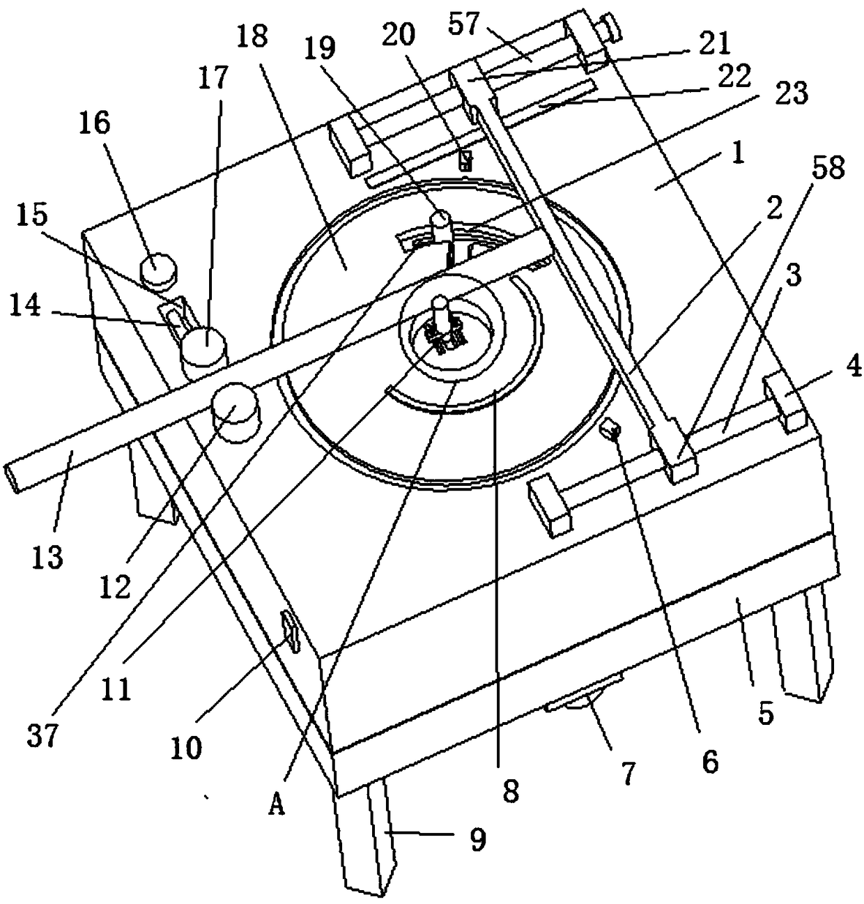
[0003] But this kind of operation is very cumbersome and not very convenient to use, so the efficiency is low, the manpower is wasted, the bending can not achieve the ideal effect, and it is easy to cause the operator to feel fatigued, and the existing steel bending device is difficult to adjust the different thickness The steel bar is bent, the angle generated during bending is not easy to fix, and the angle is not accurate, the length of the bend cannot be adjusted, and the arc of the steel bar is fixed, and the function is single, so we make a decision on this Improvement and propose a steel bar bending device for building construction

Method used


Image

  • Work method of rebar bending device for building construction
  • Work method of rebar bending device for building construction
  • Work method of rebar bending device for building construction

Examples


Embodiment Construction

[0021] The following will clearly and completely describe the technical solutions in the embodiments of the present invention with reference to the accompanying drawings in the embodiments of the present invention. Obviously, the described embodiments are only some, not all, embodiments of the present invention.

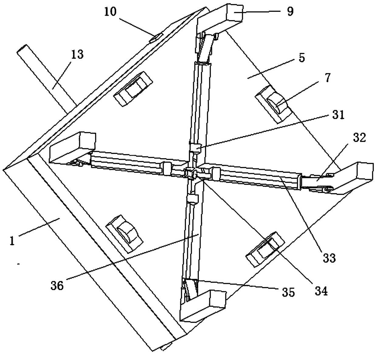
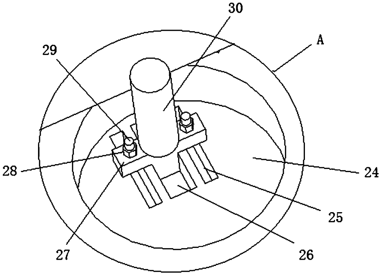
[0022] refer to Figure 1-6 , a steel bar bending device for building construction, comprising a first support plate 5, a T-shaped hole 56 is provided in the middle of the upper end of the first support plate 5, and a second motor 43 is provided inside the T-shaped hole 56, and the second motor 43 The output end of the first support plate 5 is provided with a second bevel tooth 42, and the lower end of the first support plate 5 is symmetrically provided with a square groove 36, and one end of the square groove 36 is rotatably connected with the support leg 9 through a pin shaft, and the other end of the square groove 36 is provided with a mounting block 31, the insid...


PUM


Abstract

The invention relates to the technical field of buildings, in particular to a work method of a rebar bending device for building construction. The work method involves a first supporting plate, and ashell is arranged at the upper end of the first supporting plate. A rotating plate is arranged at the upper end of a second supporting column, and a T-shaped block is arranged in a sliding groove. A third movable column is arranged at the upper end of the T-shaped block, and T-shaped grooves are symmetrically formed in the upper end of a second supporting plate. An arc-shaped groove is formed in one side of the upper end of the rotating plate, and a second movable column is arranged in the arc-shaped groove. A fixed column is arranged on one side of the upper end of the shell, and a first threaded rod is arranged between a separation plate and a fixed base. A first movable column is arranged at the upper end of a third threaded sleeve, and the upper end of a rotary shaft penetrates the shell to be connected with a first rotary disc. According to the work method, rebars can be bent into different radians, the rebars of different bending lengths can be bent, and the structure is simple;adjustment and use are convenient, the labor efficiency can be reduced, and the production process can be accelerated; and time and labor are saved, and the work method is worthy of use and popularization.

Description

technical field [0001] The invention relates to the field of building technology, in particular to a working method of a steel bar bending device for building construction. Background technique [0002] With the gradual development of my country's economic construction, large-scale construction projects are being carried out all over the country to build various residential buildings, office buildings, road works and other projects under construction. For the construction industry, steel bars are basically used, and steel bars are not important for buildings. It goes without saying that especially the steel skeleton contained in the building is directly related to the internal quality of the building. Before binding the steel bars, it is necessary to cut the long steel bars into the required size, then bend them into a fixed shape, and finally tie them into shape. Pouring concrete. When bending a certain length of steel bar, a manual bending machine is generally used, which i...

Claims


Application Information

Patent Timeline
Patent Type & Authority Applications(China)
IPC IPC(8): B21F1/00B21C51/00
CPCB21C51/00B21F1/00
Inventor 郭凤琴杨丽杨强强
Owner 广东鸿福城建设有限公司
Learn More