
Novel paint spraying equipment

A painting equipment and a new type of technology, applied in the field of painting, can solve the problems of low efficiency of manual labor, harmful to health, uneven painting, etc., and achieve the effect of reducing labor intensity of workers, reducing operation steps, and preventing painting deviation

Inactive Publication Date: 2018-07-17
南宁盛世凌云电子科技有限公司
View PDF6 Cites 1 Cited by
  • Summary
  • Abstract
  • Description
  • Claims
  • Application Information

AI Technical Summary

Problems solved by technology

Traditional manual labor has low efficiency, uneven painting and is harmful to health. At present, some automatic painting equipment only paints the workpiece from one direction. After one side is painted and dried, it is turned over and painted on the other side. The steps are cumbersome and the efficiency is high. low

Method used


Image

  • Novel paint spraying equipment
  • Novel paint spraying equipment
  • Novel paint spraying equipment

Examples


Embodiment Construction

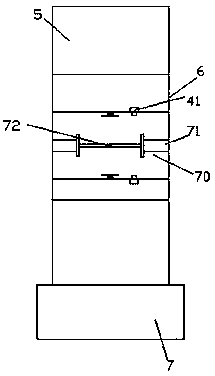
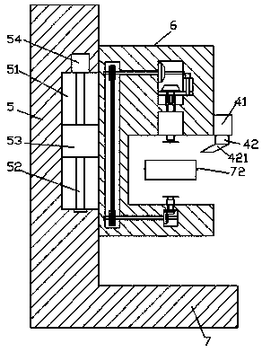
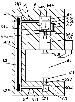
[0021] Such as figure 1 , figure 2 , image 3 and Figure 4 As shown, a new type of painting equipment of the present invention includes a base body 7, a support column 5 fixed on the rear side of the base body 7, and a painting structure 6 arranged on the front side of the support column 5, and the painting structure 6 The inside of the front side is provided with a spraying operation tank 61, and a first electric rotating machine 68 is fixedly arranged in the top surface of the painting spraying operation tank 61, and the bottom of the first electric rotating machine 68 is connected with an upper spray head 610, and the upper spray head 610 is opposite to each other. The inner bottom surface of the painting operation tank 61 is provided with a lower nozzle 611, the interior of the painting structure 6 above the first electric rotating machine 68 is provided with an alternate chamber 64, and the interior of the painting structure 6 below the upper nozzle 610 is provided wi...


PUM


Abstract

The invention discloses novel paint spraying equipment. The novel paint spraying equipment comprises a base body, a supporting column and a paint spraying structure, wherein the supporting column is arranged at the rear side surface of the base body; the paint spraying structure is arranged at the front side of the supporting column; the front side surface of the paint spraying structure is internally provided with a paint spraying operation groove; the internal top surface of the paint spraying operation groove is internally fixedly provided with a first electromotor; the bottom of the firstelectromotor is connected with an upper spraying head in a matching manner; the internal bottom surface, opposite to the upper spraying head, of the paint spraying operation groove is provided with alower spraying head; a part, above the first electromotor, of the paint spraying structure is internally provided with an alternating chamber; a part, below the upper spraying head, of the paint spraying structure is internally provided with a first transfer chamber; a part, behind the paint spraying operation groove, of the paint spraying structure is internally provided with a second transfer chamber which is arranged in a manner of extending up and down; the front end of the alternating chamber is internally provided with a guide groove; the guide groove is internally provided with a firstscrew rod arranged in a manner of extending up and down; and the internal bottom surface of the alternating chamber is provided with an inner locking sleeve of which the bottom end is rotationally matched and connected with the top end of the first electromotor. The novel paint spraying equipment disclosed by the invention is simple in structure, can realize double-size paint spraying, reduces thepaint spraying difficult, improves the paint spraying precision and saves time and efforts.

Description

technical field [0001] The invention relates to the technical field of painting, in particular to a novel painting equipment. Background technique [0002] Many workpieces need to be painted, which not only plays the role of protection but also beautifies the decoration. Traditional manual labor has low efficiency, uneven painting and is harmful to health. At present, some automatic painting equipment only paints the workpiece from one direction. After one side is painted and dried, it is turned over and painted on the other side. The steps are cumbersome and the efficiency is high. low. Contents of the invention [0003] The technical problem to be solved by the present invention is to provide a new type of painting equipment, which can solve the above-mentioned problems in the prior art. [0004] The present invention is achieved through the following technical solutions: a new type of painting equipment of the present invention, comprising a base, a support column fix...

Claims


Application Information

Patent Timeline
IPC IPC(8): B05B13/04B05B15/68B05B13/02B05B15/00
CPCB05B13/0421B05B13/02B05B15/00
Inventor 何杨波
Owner 南宁盛世凌云电子科技有限公司
Learn More