
Binocular vision experimental cloud deck with freely adjustable baseline position

A binocular vision, free technology, used in image communication, electrical components, stereo systems, etc., can solve the problems of inflexibility, heavy weight, large volume, etc., and achieve the effect of easy handling and simple structure

Pending Publication Date: 2018-07-13
TIANJIN UNIV OF COMMERCE
View PDF0 Cites 5 Cited by
  • Summary
  • Abstract
  • Description
  • Claims
  • Application Information

AI Technical Summary

Problems solved by technology

[0004] In order to overcome the shortcomings of the existing wide-baseline binocular vision platform, which are bulky, inflexible, and heavy, the present invention provides a binocular vision experiment platform whose baseline position can be adjusted freely

Method used


Image

  • Binocular vision experimental cloud deck with freely adjustable baseline position
  • Binocular vision experimental cloud deck with freely adjustable baseline position
  • Binocular vision experimental cloud deck with freely adjustable baseline position

Examples


Embodiment Construction

[0020] The present invention will be further described below in conjunction with the accompanying drawings.

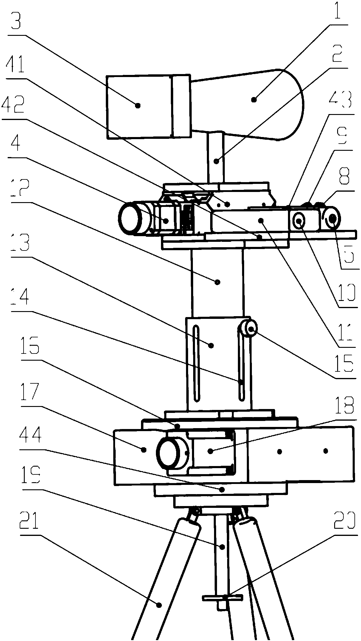
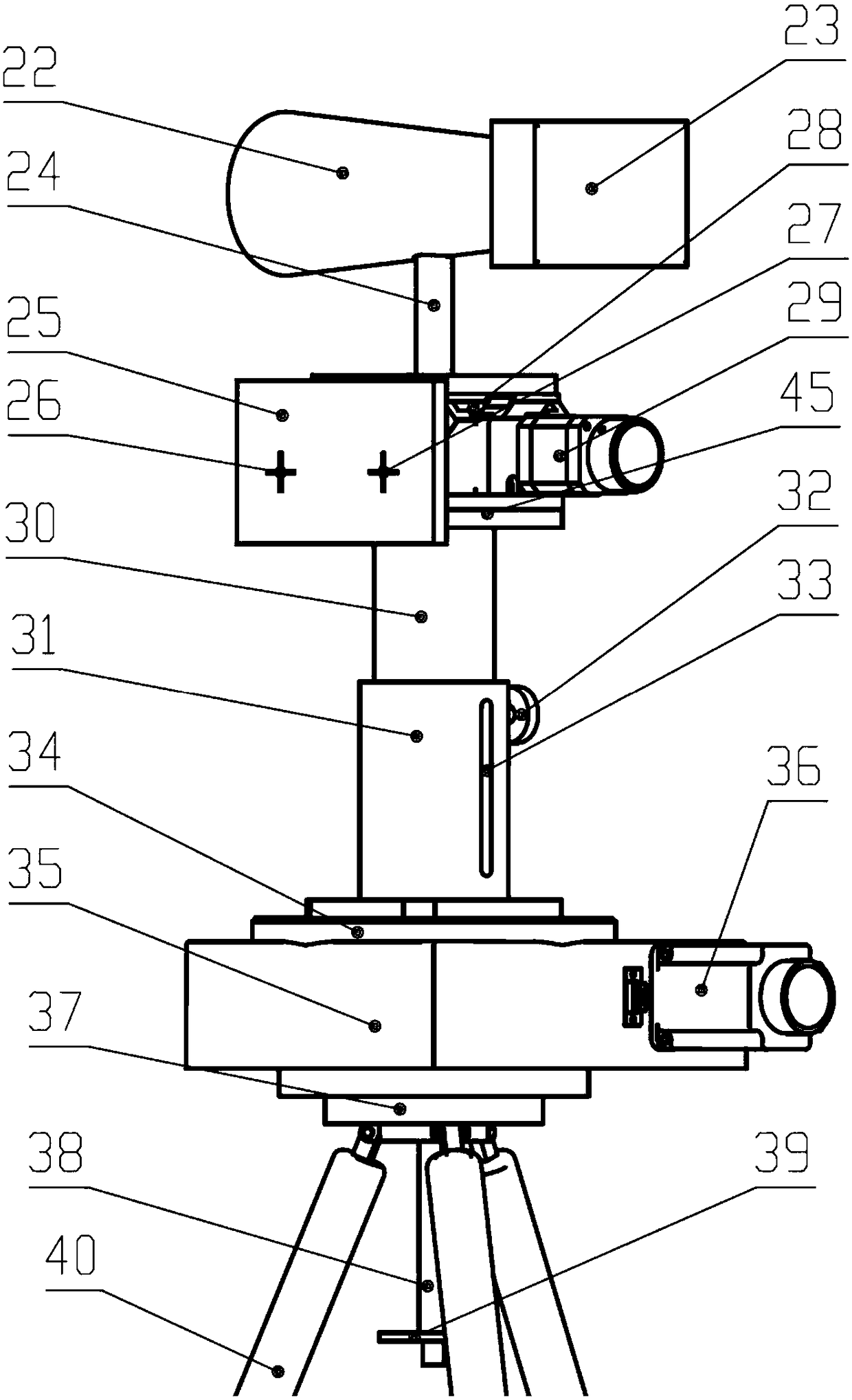
[0021] A binocular vision experiment platform with freely adjustable baseline position, consisting of two independent parts, the vision device with laser calibration on the left and the vision device with bullseye on the right.

[0022] Such as Figure 1-2 As shown, the visual device with laser calibration includes, the first lens 1 and the first camera 3, the first lens 1 and the first camera 3 are fixed on the first pitching device 41 through the first support rod 2, the first pitching device 41 The pitching motion of the first lens 1 is realized by the rotation of the first worm gear device, and the first stepping motor 4 drives the worm in the first worm gear device to rotate.

[0023] The side of the first tilting device 41 is fixedly connected to the laser range finder 11 and the laser sight 43 through the first bottom plate 42 . The laser sight 43 adjusts the ...


PUM


Abstract

The invention discloses a binocular vision experimental cloud deck with a freely adjustable baseline position. A vision device with laser calibration is arranged on a left side of the binocular visionexperimental cloud deck, and a vision device with a bullseye is arranged on a right side of the binocular vision experimental cloud deck; the vision device with laser calibration comprises a first lens and a first camera, the first lens and the first camera are fixed by first supporting rods on a first pitching device, the first pitching device realizes the pitching motion of the first lens by the rotation of a first worm gear device, and a first stepping motor drives the worm in the first worm gear device to rotate; the visual device with the bullseye comprises a second lens and a second camera, the second lens and the second camera are fixed by second supporting rods on a second pitching device, the second pitching device realizes the pitching motion of the second lens through a secondworm gear device, and a third stepping motor drives the worm in the second worm gear device to rotate. The binocular vision experimental cloud deck disclosed by the invention has the freely adjustableposition, a simple structure and convenience for carrying, and is suitable for binocular vision experiments of large buildings in the field.

Description

technical field [0001] The invention relates to the field of observation equipment, and more specifically relates to a binocular vision experiment cloud platform. Background technique [0002] The binocular vision pan / tilt in reality has two cameras, and the two cameras observe the same observation object at the same time, which can realize the function of stereoscopic imaging. [0003] The two cameras of the traditional wide-baseline binocular vision pan / tilt are generally assembled together, and the baseline distance adjustment between the cameras is limited. At the same time, for shooting distant objects, two large cameras and lenses are used. If assembled together, This design scheme cannot overcome the disadvantages of large volume, complex structure, and difficulty in flexible handling, and is not suitable for field binocular vision experiments such as large buildings. Contents of the invention [0004] In order to overcome the shortcomings of the existing wide-base...

Claims


Application Information

Patent Timeline
IPC IPC(8): H04N13/239H04N13/246H04N13/296
Inventor 王勇葛宝臻张晓川计宏伟陈雷曹卓尧曹兴业石孟昆高丽盼任豪杰
Owner TIANJIN UNIV OF COMMERCE
Learn More