Preemptive multiplexed serial port automatic switching method and device

An automatic switching and preemptive technology, which is applied in the field of serial communication, can solve the problems of serial communication, inconvenient maintenance, difficult for users, etc., and achieve the effect of fewer components and ensuring reliability

Inactive Publication Date: 2018-07-13
XIAMEN YAXON NETWORKS CO LTD
View PDF4 Cites 3 Cited by
  • Summary
  • Abstract
  • Description
  • Claims
  • Application Information

AI Technical Summary

Problems solved by technology

[0002] In the single board of communication equipment, the serial interface is the most commonly used human-computer interaction interface. However, the number of serial ports of the MCU chip in some equipment single boards is currently limited. Usually, these serial ports communicate with the sensors inside the device (serial communication mode), and are used When it is used up, the serial port can no longer be used to communicate with external serial devices, so it is also impossible to perform local upgrades, serial port online debugging, or connect to the serial port screen for parameter setting and other operations through the serial port.
[0003] At present, there are mainly the following ways to solve the above problems: 1. Expand the required serial port with a serial port expansion chip or MCU. The disadvantage of this method is to increase the hardware cost and the complexity of the software; 2. Add jumper caps or The switching method is to manually switch between the serial port of the MCU chip and the sensor and the external serial port. Although this method is simple, it is very inconvenient to maintain. It is difficult for users to distinguish which serial port to use for connection. The reliability is poor, and the device must be restarted when the external serial device is connected (the communication protocol between the MCU chip and the external serial device and the internal serial communication must be different)

Method used


Image

  • Preemptive multiplexed serial port automatic switching method and device

Examples


Embodiment Construction

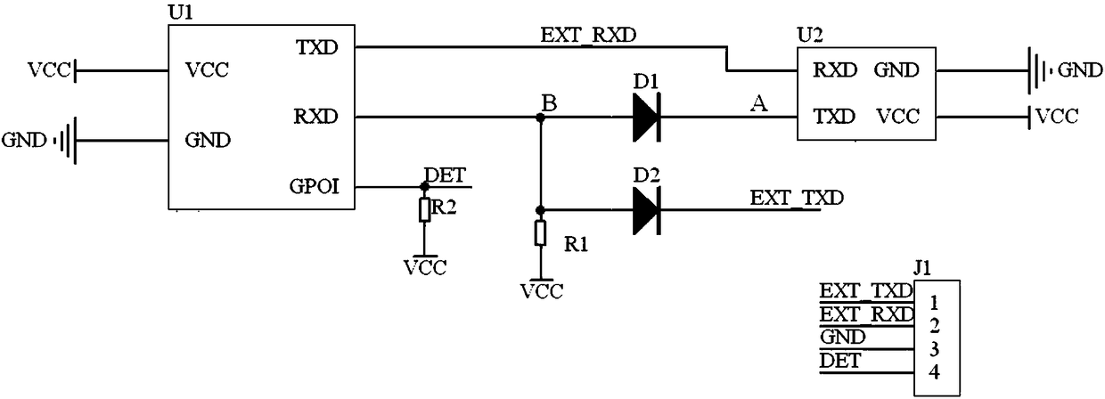
[0030] see figure 1 As shown, the embodiment of the present invention provides a method for automatic switching of preemptive multiplexed serial ports, which involves MCU chip U1, sensor U2 and external serial port device J1, wherein MCU chip U1 and sensor U2 are set on the single board of the device, and the default Under normal circumstances, the MCU chip U1 communicates with the sensor U2. When operations such as local upgrade, serial port online debugging, or serial port screen for parameter setting are required, the external serial port device needs to be plugged into the MCU chip and communicate.

[0031] Specifically, the MCU chip U1 includes a power supply terminal VCC, a ground terminal GND, a serial port data input terminal RXD, a serial port data output terminal TXD, and an input and output terminal GPOI; the sensor U2 includes a power supply terminal VCC, a ground terminal GND, and a serial port data input terminal. terminal RXD and serial data output terminal TXD;...


PUM


Abstract

The invention discloses a preemptive multiplexed serial port automatic switching method and device. The method comprises the steps of setting an input output end of an MCU chip in equipment as a flagbit, connecting the input output end with a power supply through a second resistor and leading out a first suspended end; connecting a serial port data input end of the MCU chip with a serial port data output end of a sensor in the equipment and a second suspended end through a first diode and a second diode respectively, and connecting positive electrodes of the first diode and the second diodewith the serial port data input end of the MCU chip; connecting the serial port data input end of the MCU chip with the power supply through a first resistor; and connecting a serial port data outputend of the MCU chip with a serial port data input end of the sensor. After the external serial port equipment is manually inserted, communication can be automatically performed with the inserted equipment, so that a channel automatic switching function is realized; and after the external serial port equipment is pulled out, communication is performed with the sensor again, so that a preemptive multiplexed serial port automatic switching function is realized.

Description

technical field [0001] The invention relates to the technical field of serial port communication, in particular to a method and device for automatic switching of preemptive multiplexed serial ports. Background technique [0002] In the single board of communication equipment, the serial interface is the most commonly used human-computer interaction interface. However, the number of serial ports of the MCU chip in some equipment single boards is currently limited. Usually, these serial ports communicate with the sensors inside the device (serial communication mode), and are used When it is used up, the serial port can no longer be used to communicate with external serial devices, so it is also impossible to perform local upgrades, serial port online debugging, or connect to the serial port screen for parameter setting and other operations through the serial port. [0003] At present, there are mainly the following types to solve the above problems: 1. Expand the required seri...

Claims


Application Information

Patent Timeline
Patent Type & Authority Applications(China)
IPC IPC(8): G06F13/40
CPCG06F13/4022
Inventor 廖丽辉林志强黄亨明卢文辉张婉双
Owner XIAMEN YAXON NETWORKS CO LTD
Why Eureka
Try Eureka