
Ceramic MEMS pressure sensor

A pressure sensor and ceramic technology, applied in the direction of measuring fluid pressure, measuring fluid pressure through electromagnetic components, instruments, etc., can solve the problems of low product accuracy, small output signal, non-interchangeability, etc., and achieve high measurement accuracy and strong output signal , good stability

Pending Publication Date: 2018-07-10
SHENZHEN READSENSOR TECH CO LTD
View PDF0 Cites 4 Cited by
  • Summary
  • Abstract
  • Description
  • Claims
  • Application Information

AI Technical Summary

Problems solved by technology

[0004] Ceramic piezoresistive pressure sensors still have two insurmountable defects in practical applications: 1. The output signal is too small, generally only 2-3mV / V, and the output signals of each sensor are not completely consistent and cannot be interchanged
2. The accuracy of the product is low and the stability is not good in the pressure range below 500Kpa

Method used


Image

  • Ceramic MEMS pressure sensor
  • Ceramic MEMS pressure sensor

Examples


Embodiment Construction

[0027] It should be noted that, in the case of no conflict, the embodiments in the present application and the features in the embodiments can be combined with each other. The present invention will be further described in detail below in conjunction with the drawings and specific embodiments.

[0028] If there are directional indications (such as up, down, left, right, front, back...) in the embodiments of the present invention, they are only used to explain the relative positions of the components in a certain posture (as shown in the drawings) relationship, motion, etc., if the particular pose changes, the directional indication changes accordingly.

[0029] In addition, in the present invention, the descriptions involving "first", "second" and so on are only for the purpose of description, and should not be understood as indicating or implying their relative importance or implicitly indicating the quantity of the indicated technical features. Thus, the features defined as ...


PUM


Abstract

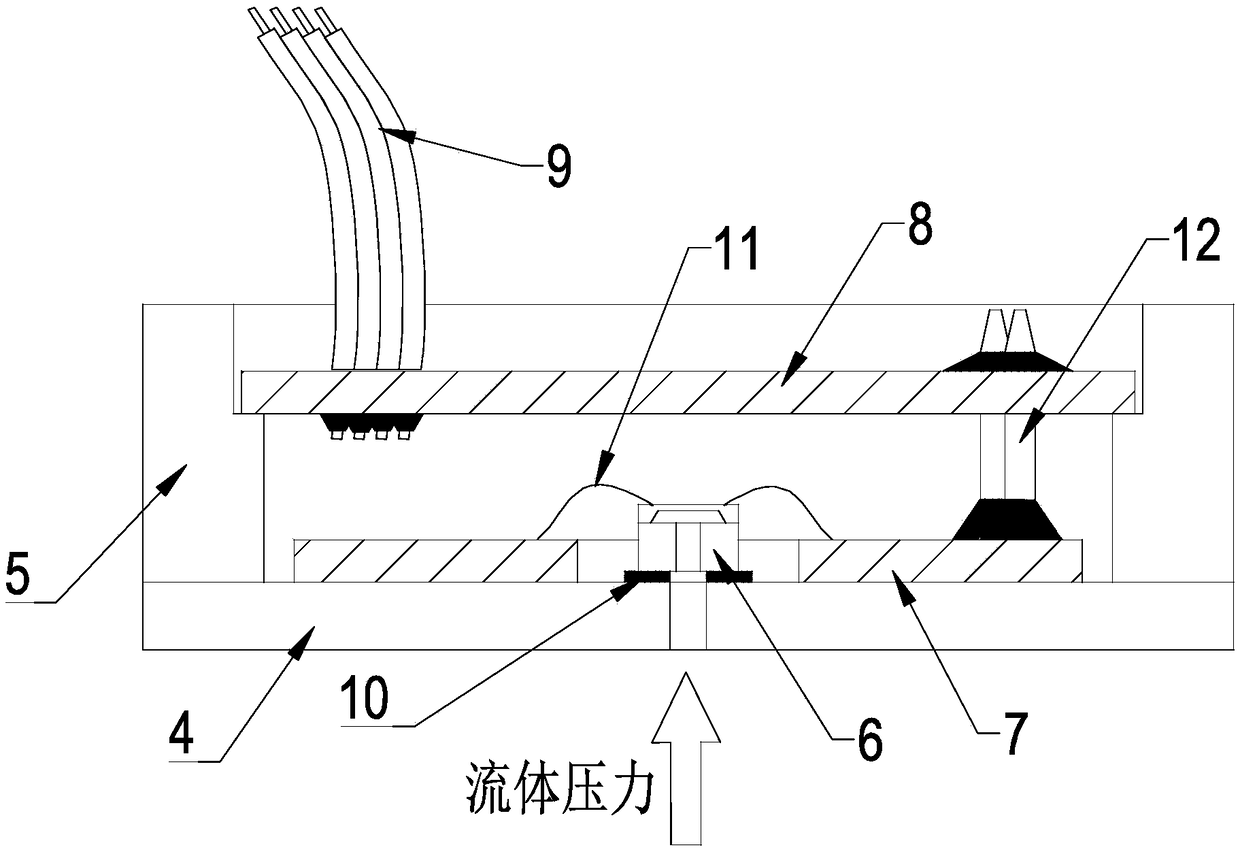
Embodiments of the invention disclose a ceramic MEMS pressure sensor. The ceramic MEMS pressure sensor comprises a ceramic substrate, a ceramic circular ring, an MEMS pressure chip, a bonding circuitboard, a signal conditioning circuit board and a cable, wherein the ceramic substrate is provided with a through hole, and the ceramic circular ring is arranged on the ceramic substrate; the MEMS pressure chip is arranged on the ceramic substrate in a sealing manner by virtue of sealing adhesive, and an intermediate hole of the MEMS pressure chip is communicated with a through hole on the ceramicsubstrate; the bonding circuit board is arranged on the ceramic substrate, and the bonding circuit board is electrically connected with the MEMS pressure chip; the signal conditioning circuit board iselectrically connected with the bonding circuit board; and the cable is electrically connected with the signal conditioning circuit board. According to the embodiments of the invention, the MEMS pressure ship is used as a pressure sensitive element, and the ceramic is used as a sealing structure of a skeleton, so that the problems that the output signal is weak, the stability is poor and the accuracy is poor can be solved, and a technical effect of strong output signal, high measuring accuracy and good stability can be achieved.

Description

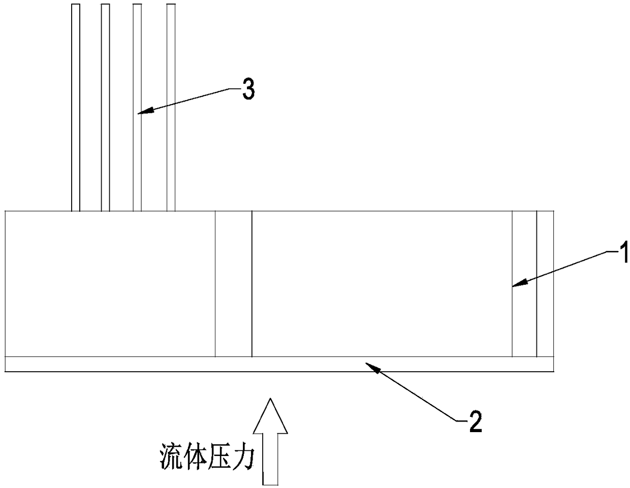
technical field [0001] The invention relates to the technical field of manufacturing high-precision pressure sensors, in particular to a ceramic MEMS pressure sensor. Background technique [0002] Ceramic piezoresistive pressure sensor is the most widely used pressure sensor at present. Its advantages are low cost, good rigidity, corrosion resistance, and compatibility with most fluid media. After years of development, it has formed a universally recognized Standard size, due to the large amount of use, its supporting parts have also formed the advantages of standardization and low cost. [0003] Traditional ceramic piezoresistive pressure sensor structure such as figure 1 As shown, its working principle is: external fluid pressure is applied to the ceramic piezoresistive diaphragm 2, and the resistance value etched on the ceramic piezoresistive diaphragm 2 changes accordingly, and the changed value is transmitted through the corresponding circuit built in the ceramic shell...

Claims


Application Information

Patent Timeline
Patent Type & Authority Applications(China)
IPC IPC(8): G01L9/06
CPCG01L9/065
Inventor 单建利陈军
Owner SHENZHEN READSENSOR TECH CO LTD
Learn More