Pavement drainage structure

A drainage structure and drainage well technology, which is applied to drainage structures, water supply devices, waterway systems, etc., can solve the problems of clogged drainage efficiency, reduction, and insufficient stability of drainage efficiency, and achieve the effect of stable drainage and not easy to block

Inactive Publication Date: 2018-07-10
WENZHOU HUAYI MUNICIPAL ENG
View PDF5 Cites 8 Cited by
  • Summary
  • Abstract
  • Description
  • Claims
  • Application Information

AI Technical Summary

Problems solved by technology

[0003] like figure 1 Shown is a kind of drainage grille, the leakage holes 111 of the drainage grille are relatively dense, which can prevent garbage from entering the drainage well and affect the urban drainage pipeline, and at the same time can lead the water flow into the drainage well. When the drainage structure of the road is in the middle, the water leakage hole 111 is easily blocked by garbage and the drainage efficiency is reduced, so that the drainage efficiency is not stable enough

Method used


Image

  • Pavement drainage structure
  • Pavement drainage structure
  • Pavement drainage structure

Examples


Embodiment Construction

[0032] The present invention will be described in further detail below in conjunction with the accompanying drawings.

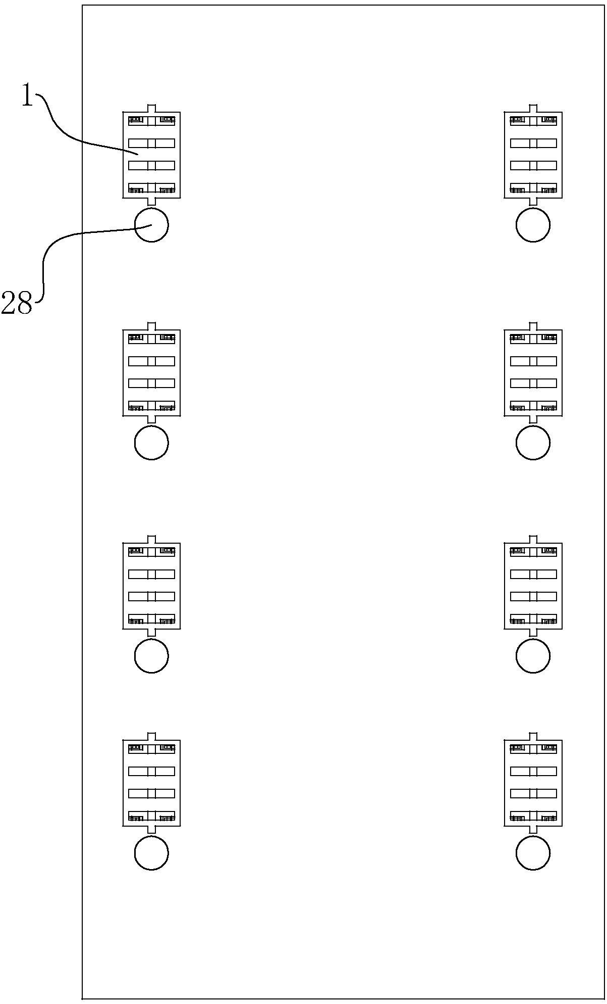
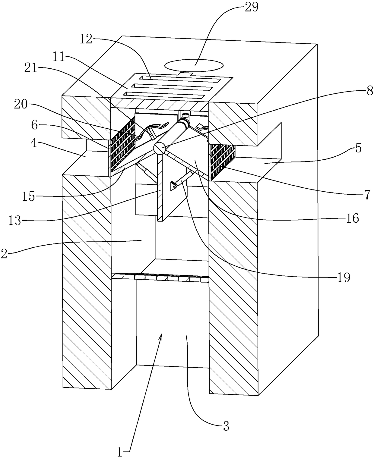
[0033] This embodiment discloses a pavement drainage structure, such as figure 2 , image 3 As shown, a plurality of drainage wells 1 are arranged on both sides of the road surface, and the bottom of the drainage wells 1 is connected with the urban drainage pipeline. For the opposite second side wall 3, the left drainage pipe 4 and the right drainage pipe 5 are respectively opened on the two first side walls 2, and the left drainage pipe 4 and the right drainage pipe 5 are all connected with the urban drainage pipeline, and the left drainage One end of the pipeline 4 and the right drainage pipeline 5 connected to the well is fixed with a left filter grid 6 and a right filter grid 7 respectively, which are used to prevent garbage from entering the left drainage pipeline 4 and the right drainage pipeline 5 and blocking the urban drainage pipeline.

[0034] Suc...


PUM


Abstract

The invention discloses a pavement drainage structure. According to the technical scheme, the pavement drainage structure is characterized in that a protection cover is arranged at a wellhead of eachdrainage well, water leaking holes are formed in the protection cover, drainage pipelines are connected on side walls of the drainage well, a filter part is arranged in the connected position of eachdrainage pipeline and the drainage well, and a guiding mechanism for guiding rainwater to the drainage pipelines is arranged in the drainage well and can transfer garbage filtered out by the filter parts, so that the filter parts cannot be blocked by the garbage. The pavement drainage structure has functions of low probability of blockage and stable drainage efficiency.

Description

technical field [0001] The invention relates to the field of road surface drainage, more specifically it relates to a road surface drainage structure. Background technique [0002] In the drainage structure of municipal roads in the prior art, drainage wells connected to the municipal drainage system are usually arranged on both sides of the road, and drainage grids are installed at the openings of the drainage wells. In rainy days, the accumulated water on the municipal roads will flow to the drainage grille and be discharged into the municipal drainage system. [0003] Such as figure 1 Shown is a kind of drainage grille, the leakage holes 111 of the drainage grille are relatively dense, which can prevent garbage from entering the drainage well and affect the urban drainage pipeline, and at the same time can lead the water flow into the drainage well. When the drainage structure of the road is in the middle, the water leakage hole 111 is easily blocked by garbage and the ...

Claims


Application Information

Patent Timeline
IPC IPC(8): E03F5/04E03F5/06E03F5/14
CPCE03F5/0401E03F5/0404E03F5/06E03F5/14
Inventor 陈裕峰刘雄娇叶献骏
Owner WENZHOU HUAYI MUNICIPAL ENG
Why Eureka
Try Eureka