


Quick Research
Generate reliable direction feasibility study reports for your R&D in just a few steps.

Technical Q&A
Discover and master advanced knowledge NOW. Basics, ideas, possibilities, all at once.

Find Solutions
As an expert in R&D theories, this can generate solutions to your technical problems instantly.

Evaluate Feasibility
Analyze your overall solution with one click, know your potential R&D risks in advance.

Monitor Landscape
Get weekly tech updates, stay abreast of the latest tech innovations and key insights.
A high-speed optical receiver test evaluation board structure and its test system
An optical receiver and board structure technology, applied in the field of optical communication, to achieve the effect of improving impedance matching characteristics, reducing device testing time, and improving accuracy
- Summary
- Abstract
- Description
- Claims
- Application Information
AI Technical Summary
Problems solved by technology
Method used
Image

Examples
Embodiment 1
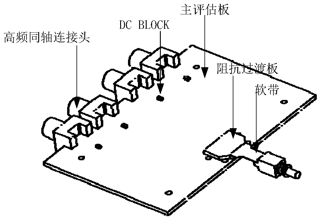
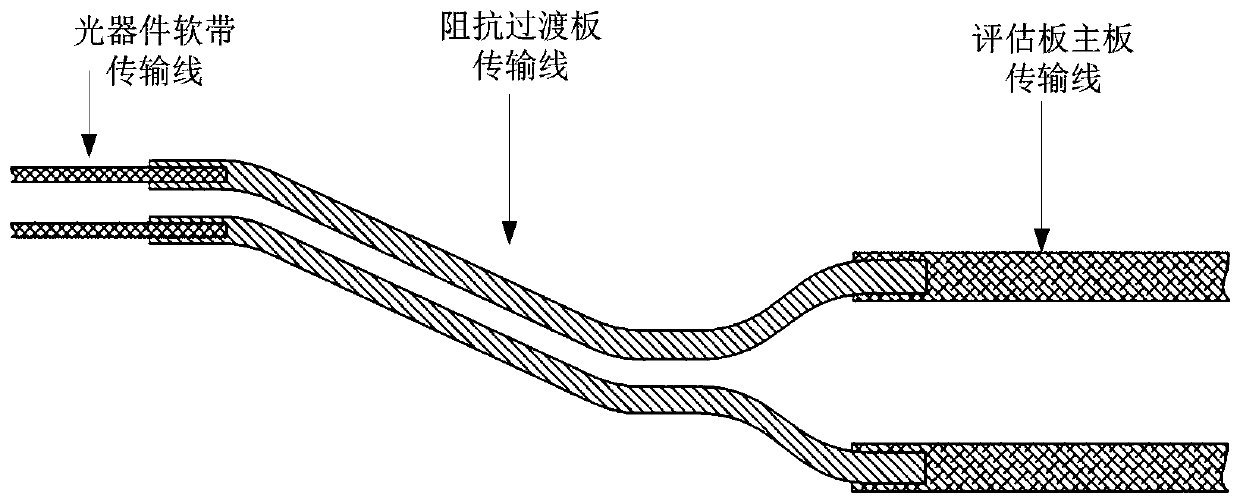
[0047] Embodiment 1 of the present invention provides an evaluation board structure for high-speed optical receiver testing, such as figure 1 As shown, including the impedance transition board and the main evaluation board, the signal line width of the soft band of the optical receiver connected to the impedance transition board is W1, and the line width in the main evaluation board is W2, as shown in figure 2 As shown, specifically:
[0048] The impedance transition board is arranged on the main evaluation board, one side is coupled with the main evaluation board; the other side is used for coupling with the soft band of the optical receiver;
[0049] The parameter value of the line width W3 of the impedance transition board is set between the signal line width W1 of the soft band and the line width W2 of the main evaluation board.
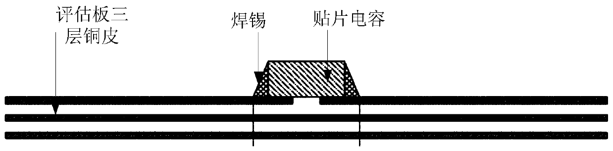
[0050] The embodiment of the present invention proposes an evaluation board structure with higher impedance matching efficiency, wherein an im...
Embodiment 2
[0063] The embodiment of the present invention also provides a sensitivity and overload test system of a multi-channel high-speed optical receiver, the test system uses the evaluation board structure as described in Embodiment 1, specifically, as Figure 6 and Figure 7 As shown, the test system includes a multi-wavelength optical signal transmitting unit 110, a parallel optical power control unit 120 and a parallel high-frequency signal receiving and processing unit 130, specifically:
[0064] The multi-wavelength optical signal transmitting unit 110 is used to generate an optical signal for testing sensitivity or to generate an optical signal for testing overload, and send it to the parallel optical power control unit 120;
[0065] The parallel high-frequency signal receiving and processing unit 130 includes a multi-channel optical receiver 131, a multi-channel high-speed evaluation board 132 and a multi-channel high-speed bit error detector 133, wherein the multi-channel op...
PUM
 Abstract
Description
Claims
Application Information
 - R&D Engineer
- R&D Manager
- IP Professional
- Industry Leading Data Capabilities
- Powerful AI technology
- Patent DNA Extraction
Browse by: Latest US Patents, China's latest patents, Technical Efficacy Thesaurus, Application Domain, Technology Topic, Popular Technical Reports.
© 2024 PatSnap. All rights reserved.Legal|Privacy policy|Modern Slavery Act Transparency Statement|Sitemap|About US| Contact US: help@patsnap.com