
Electric power distribution equipment

A power distribution equipment and power technology, applied in electrical components, substation/switch layout details, substation/switchgear cooling/ventilation, etc. problem, to achieve the effect of simple structure and convenient operation

Inactive Publication Date: 2018-07-06
佛山市畅意机械租赁有限公司
View PDF0 Cites 0 Cited by
  • Summary
  • Abstract
  • Description
  • Claims
  • Application Information

AI Technical Summary

Problems solved by technology

[0002] At present, the heat dissipation method of the power distribution cabinet is mainly through the air conditioner in the machine room, and the heat dissipation capacity is poor, especially when many power distribution cabinets are placed in a single machine room, the heat dissipation cannot meet the needs of use. Most of the electric cabinets are of sealed structure, which leads to poor heat dissipation of the power distribution cabinet when the power distribution cabinet is running under high load or the weather is hot, or the ambient temperature is high. electrical equipment

Method used


Image

  • Electric power distribution equipment
  • Electric power distribution equipment
  • Electric power distribution equipment

Examples


Embodiment Construction

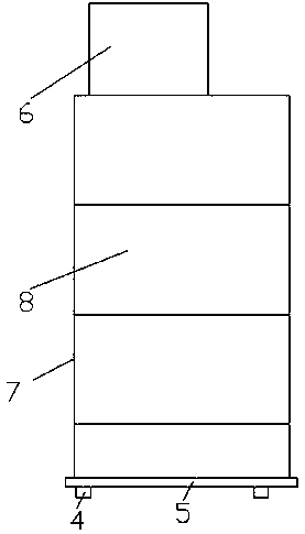
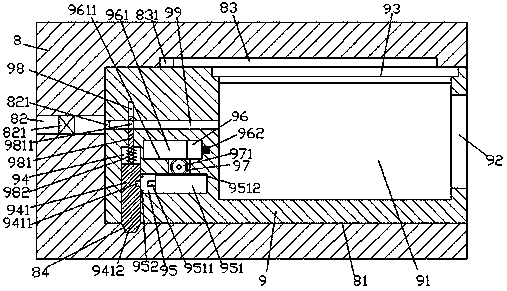
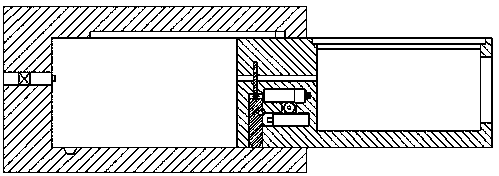
[0015] Such as figure 1 , figure 2 with image 3 As shown, a power distribution equipment of the present invention includes a power distribution cabinet 8, the top end of the power distribution cabinet 8 is fixed with a heat driving device 6, and the bottom end of the power distribution cabinet 8 is provided with a supporting base 5. Four foot pads 4 are installed on the end surface of the bottom of the support base plate 5, and the right end surface of the power distribution cabinet body 8 is provided with a storage cavity 81, and the installation box body 9 is slidably connected to the storage cavity 81 , the inner wall of the power distribution cabinet 8 on the left side of the storage chamber 81 is provided with an input pipe 82 extending from left to right, and the right end of the input pipe 82 is fixed with a pipe extending into the storage chamber 81. The latch opening 821, the bottom end surface of the storage cavity 81 is provided with an inclined cavity 84, and t...


PUM


Abstract

The invention discloses electric power distribution equipment. The electric power distribution equipment comprises a power distribution cabinet body; a heat dispelling apparatus is fixedly arranged onthe top end plane of the power distribution cabinet body; a supporting bottom plate is arranged on the bottom end plane of the power distribution cabinet body; four foot pads are mounted on the bottom end plane of the power distribution cabinet body; an accommodating cavity is formed in the right side end plane of the power distribution cabinet body; a mounting box body is glidingly matched and connected in the accommodating cavity; an input pipe which can extend left and right is arranged in the inner wall body of the power distribution cabinet body on the left side of the accommodating cavity; a bolt port which extends into the accommodating cavity is fixedly formed in the tail end of the right side of the input pipe; an inclined cavity is formed in the bottom end plane of the accommodating cavity; a placement groove is formed in the top end plane of the right side of the mounting box body; and an air inlet hole, which is formed left and right, is arranged in the inner wall body ofthe mounting box body on the left side of the placement groove. By virtue of the electric power distribution equipment, a locking and fixing operation can be automatically controlled and stabilized, and automatic connection control and cooling control operations can be realized.

Description

technical field [0001] The invention relates to the field of power equipment, in particular to power distribution equipment. Background technique [0002] At present, the heat dissipation method of the power distribution cabinet is mainly through the air conditioner in the machine room, and the heat dissipation capacity is poor, especially when many power distribution cabinets are placed in a single machine room, the heat dissipation cannot meet the needs of use. Most of the electric cabinets are of sealed structure, which leads to poor heat dissipation of the power distribution cabinet when the power distribution cabinet is in high-load operation or the weather is hot, or the ambient temperature is high. electrical equipment. Contents of the invention [0003] The technical problem to be solved by the present invention is to provide a method that can solve the above-mentioned problems in the prior art. [0004] The present invention is realized through the following tec...

Claims


Application Information

Patent Timeline
Patent Type & Authority Applications(China)
IPC IPC(8): H02B1/56
CPCH02B1/565
Inventor 叶翠颖
Owner 佛山市畅意机械租赁有限公司
Learn More