refrigeration equipment

A technology of refrigeration equipment and rotating shaft, applied in household refrigeration equipment, lighting and heating equipment, cooling fluid circulation device, etc., can solve problems such as poor user experience, beam shaking, and radial movement of the rotating shaft.

Active Publication Date: 2020-11-27
BSH ELECTRICAL APPLIANCES JIANGSU +1
View PDF5 Cites 0 Cited by
  • Summary
  • Abstract
  • Description
  • Claims
  • Application Information

AI Technical Summary

Problems solved by technology

This makes the fastening effect of the buckle on the rotating shaft not good, and the rotating shaft is prone to radial movement when the beam rotates, causing the beam to shake, resulting in poor user experience

Method used


Image

  • refrigeration equipment
  • refrigeration equipment
  • refrigeration equipment

Examples


Embodiment Construction

[0029] In order to make the above objects, features and advantages of the present invention more comprehensible, specific embodiments of the present invention will be described in detail below in conjunction with the accompanying drawings.

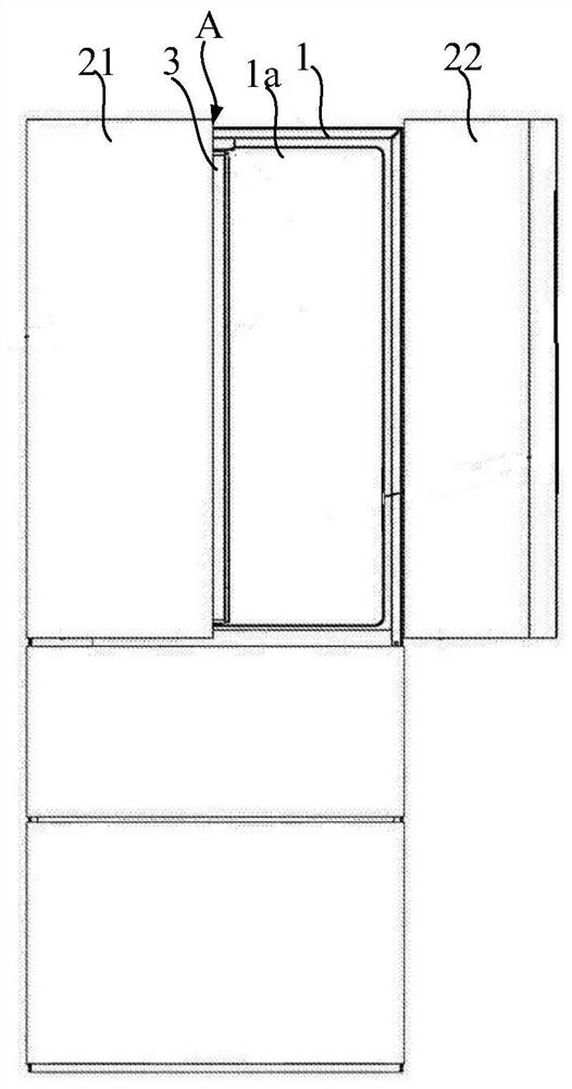
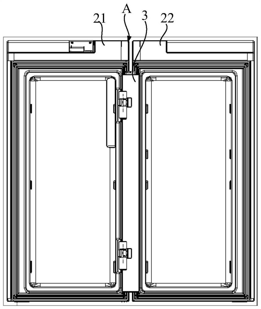
[0030] refer to Figure 1-Figure 3 , the refrigerating equipment includes: a body 1 with a front opening 1a; a first door 21 and a second door 22 that are oppositely arranged at the front opening 1a, and the first door 21 has a free end A away from its axis of rotation; a beam 3 that is rotated by Shaft 4 is pivotally connected to free end A so as to be rotatable between a retracted position and an extended position. refer to Figure 4 as shown, Figure 4 (a) is a top view when the first door 21 is closed, and the beam 3 is in an unfolded position to seal the first door 21 and the second door 22; Figure 4 (b) is a top view during the opening process of the first door 21, and the beam 3 rotates relative to the first door 21; Figure 4 ...


PUM


Abstract

A refrigeration equipment, including: a body (1) with a front opening (1a); a first door (21) and a second door (22), which are arranged oppositely at the front opening (1a). The first door (21) It has a free end (A) away from its rotation axis; the beam (3) is pivotally connected to the free end (A) through the rotation axis (4), so that it can rotate between the retracted position and the deployed position; the first positioning part (51 ), fixedly connected to the beam (3); the first positioning portion (51) has at least a portion surrounding the rotation axis (4) along the circumferential direction of the rotation axis (4) and a radially inner end (51a) facing the rotation axis (4). , the radially inner end (51a) radially defines the rotation axis (4) to the beam (3) along the rotation axis (4). Along the circumferential direction, the radially inner end (51a) forms a large overlapping area with the rotation axis (4), thereby blocking the radial movement of the rotation axis (4) in multiple directions when the beam (3) rotates, thereby effectively The beam (3) is prevented from shaking, and the user's door opening experience is improved.

Description

technical field [0001] The invention relates to the technical field of refrigeration equipment, in particular to a refrigeration equipment. Background technique [0002] An existing refrigerator comprises: a main body; a first door and a second door arranged opposite to each other, the first door has a free end far away from its rotating shaft; it is pivotally connected to the free end through the rotating shaft, so that it can be moved between the retracted position and the unfolded position. Rotate between. In the closed state of the first door, the beam is in the unfolded position to act as a seal between the first door and the second door; when the first door is opened, the beam is gradually rotated to the retracted position relative to the first door, so that the first door Open normally. [0003] Wherein, the rotating shaft is crimped to the beam by a buckle to form a radial barrier to the rotating shaft, thereby preventing the rotating shaft from falling off from th...

Claims


Application Information

Patent Timeline
Patent Type & Authority Patents(China)
IPC IPC(8): F25D23/02
CPCF25D23/02F25D23/028F25D2323/02
Inventor 任斯婷章传郭云珍
Owner BSH ELECTRICAL APPLIANCES JIANGSU
Why Eureka
Try Eureka