Tunnel drilling machine with drill rod automatic loading and unloading functions for remote control

An automatic loading and unloading and remote control technology, which is applied to drill pipes, drilling automatic control systems, drilling pipes, etc., can solve the problems of casualties, low drilling efficiency, and prone to errors, etc., and achieve high automation and high disassembly efficiency , to avoid the effect of slipping

Active Publication Date: 2018-07-06
SHANDONG UNIV OF SCI & TECH
View PDF7 Cites 11 Cited by
  • Summary
  • Abstract
  • Description
  • Claims
  • Application Information

AI Technical Summary

Problems solved by technology

[0003] Most of the existing tunnel drilling rigs do not have the function of automatically changing drill pipes, and the process of manually replacing drill pipes and water joints is a very time-consuming, labor-intensive and dangerous work
It usually takes 5-10 minutes to manually change a drill pipe, and it is completed by 2-3 people. The auxiliary ti...

Method used


Image

  • Tunnel drilling machine with drill rod automatic loading and unloading functions for remote control
  • Tunnel drilling machine with drill rod automatic loading and unloading functions for remote control
  • Tunnel drilling machine with drill rod automatic loading and unloading functions for remote control

Examples


Embodiment Construction

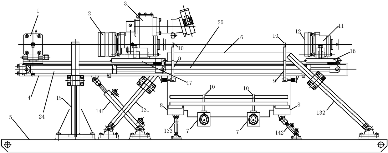
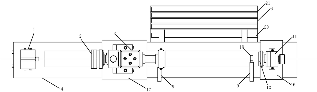
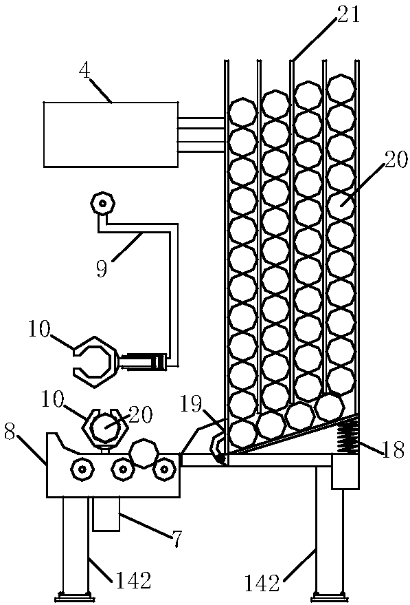
[0027] like Figure 1 to Figure 7 As shown, this embodiment provides a tunnel drilling machine for automatic loading and unloading of drill pipes for remote control, which includes a base 5, a support mechanism, a carriage 4, a drill pipe transmission unit and the like. The base 5 is connected to the carriage 4 through a support mechanism, wherein the support mechanism includes a column 15, a front support rod 131, a rear support rod 132 and a front support cylinder 141, the column 15 is arranged on the front end of the base 5, and the carriage 4 is slidably connected through a sliding sleeve Column 15, the front end of one end hinge base 5 of front support rod 131, the front end of the other end hinge carriage 4 of front support rod 131, the rear end of one end hinge base 5 of rear support rod 132, the other end hinge of rear support rod 132 The rear end of the carriage 4, the front end of one end of the front support cylinder 141 is hinged to the base 5, and the other end of...


PUM


Abstract

The invention provides a tunnel drilling machine with drill rod automatic loading and unloading functions for remote control. A base is connected with a sliding frame through a supporting mechanism, and a clamping device is arranged at the front end of the sliding frame. The front half part of the sliding frame is slidably connected with an upper drag plate, and the upper drag plate is provided with an upper gyrator. A rotor of the upper gyrator is provided with an upper clamping disc, and the front half part of the sliding frame is provided with an upper oil cylinder. The movable column end of the upper oil cylinder is connected with the upper drag plate, and the rear half part of the sliding frame is slidadbly connected with a lower drag plate. The lower drag plate is provided with a lower gyrator, a rotor of the lower gyrator is provided with a lower clamping disc. The rear half part of the sliding frame is provided with a lower oil cylinder, and the movable column end of the loweroil cylinder is connected with a lower drag plate. A rod outlet is formed in one side of the bottom of a drill rod box, one end of a transmitter is located at the rod outlet, and the other end of thetransmitter is provided with a lifting device. A cam is hinged to the other end of the transmitter, and the cam is connected with a manipulator through a connecting rod. One end of a rotary arm is hinged to the sliding frame, and the other end of the rotary arm is slidably connected with the manipulator. The tunnel drilling machine has the beneficial effect that a drill rod and a water swivel canbe automatically and efficiently mounted and dismounted under remote control.

Description

technical field [0001] The invention relates to the technical field of tunnel drilling machines, in particular to a tunnel drilling machine for automatic loading and unloading of drill pipes for remote control. Background technique [0002] About 53% of my country's coal resources are buried deeper than 1,000 meters. With the transfer of coal resources mining to the deep, the frequency and intensity of rock bursts have increased significantly, which seriously restricts the safe and efficient mining of deep resources. By drilling holes in the impact risk area, the stress concentration in the area can be effectively reduced, and the accumulated elastic strain energy can be released, thereby reducing the impact risk in the area. At present, fully hydraulic tunnel drilling rigs are commonly used in coal mines for drilling and pressure relief, which can complete basic drilling tasks. This drilling rig is also widely used in drilling constructions such as water exploration, water ...

Claims


Application Information

Patent Timeline
IPC IPC(8): E21B19/18E21B44/00
CPCE21B19/18E21B44/00Y02P70/10
Inventor 刘学生范德源谭云亮顾清恒王军徐强
Owner SHANDONG UNIV OF SCI & TECH
Why Eureka
Try Eureka