
Bending device and bending machine

A technology of bending device and bending mechanism, applied in the direction of feeding device, positioning device, storage device, etc., can solve the problems of unsmooth feeding and discharging, difficult assembly line connection, etc., and achieve the effect of simple structure and convenient use

Pending Publication Date: 2018-07-06
OMS MASCH CO LTD
View PDF0 Cites 0 Cited by
  • Summary
  • Abstract
  • Description
  • Claims
  • Application Information

AI Technical Summary

Problems solved by technology

[0003] The purpose of the present invention is to provide a bending device to solve the problems in the prior art that the feeding and discharging are not smooth and it is difficult to connect with the assembly line

Method used


Image

  • Bending device and bending machine
  • Bending device and bending machine
  • Bending device and bending machine

Examples


Embodiment Construction

[0022] Below, in conjunction with accompanying drawing and specific embodiment, the present invention is described further:

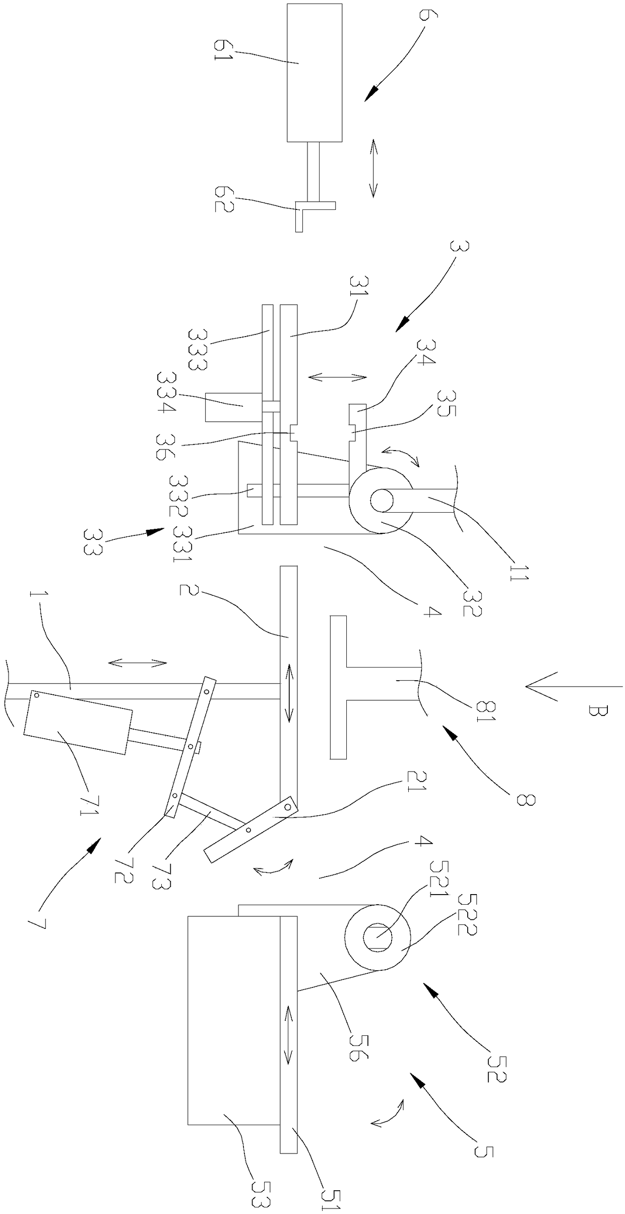
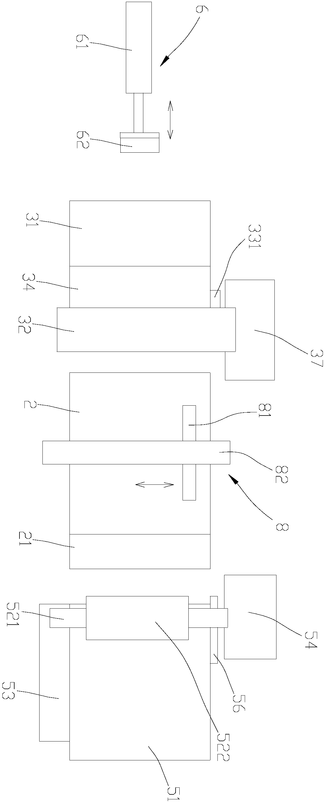
[0023] refer to figure 2 , a bending machine, comprising a base 1, the base 1 is provided with a workpiece platform 2, the front end of the workpiece platform 2 is provided with a first bending mechanism 3, and the first bending mechanism 3 includes a first bending mechanism Bending plate 31 and first turning roller 32, described first bending plate 31 turns and bends with described first turning roller 32 as the center, and described first turning roller 32 extends from one side of described workpiece table 2 to On the other side of the workpiece table 2, between the workpiece table 2 and the first rotating roller 32, a side opening 4 is provided on one side of the workpiece table 2, and the side opening 4 is used for the Describe the use of the material in and out of the workpiece table 2.

[0024] In the present invention, a first bending mechanis...


PUM


Abstract

The invention discloses a bending device. The bending device comprises a working platform, a second bending mechanism is arranged at the rear end of the working platform, the second bending mechanismcomprises a second bending plate and a second rotary roller, the second bending plate is rotatably bent taking the second rotary roller as the center, one side of the second rotary roller extends fromone side of the working platform and extends to the other side of the working platform, a side opening is formed in the portion, between the working platform and the second rotary roller, of one sideof the working platform, the side opening is used for material feeding or discharging of the working platform, the second bending mechanism further comprises a supporting mechanism capable of extending and retracting, and the supporting mechanism is arranged at the side opening and used for supporting the second rotary roller. The invention further discloses a bending machine. By means of the above structural arrangement, the material feeding and discharging of the bending machine are smoother, so that the connection with a production line can be achieved, the traditional problems of the material feeding and discharging of the bending machine are solved to help to achieve an automated production line, rotary bending is achieved through the second bending plate, the bending of workpieces can be achieved, and the bending machine is simple in structure and convenient to use.

Description

technical field [0001] The invention relates to the field of bending equipment, in particular to a bending device and a bending machine. Background technique [0002] With the development of technology, the application of devices such as heat exchangers is becoming more and more extensive. In the prior art, heat exchangers generally need to be bent and formed by a bending machine. At present, the bending machines on the market generally include a work table, the front end or the rear end of the work table is provided with a bending plate, and both sides of the work table are provided with support columns to support the two ends of the rollers. When in use, the workpiece is placed on the workpiece table from the front end of the workpiece table, and after the bending is completed, the workpiece is left from the work table from the front end or rear end of the work table. refer to figure 1 , but because both ends of the workpiece 101 (heat exchanger, etc.) generally have en...

Claims


Application Information

Patent Timeline
IPC IPC(8): B21D7/024B21D43/00B21D43/02B21D45/04B21D53/02
CPCB21D7/024B21D43/003B21D43/02B21D45/04B21D53/02
Inventor 龙晓斌洪伟东
Owner OMS MASCH CO LTD
Learn More