Stacking type dewatering structure for waste gas absorption tower

A dehydration structure and absorption tower technology, applied in the directions of dispersed particle separation, chemical instruments and methods, separation methods, etc., can solve the problems of corroding air ducts or fans, cumbersome, affecting the dehydration efficiency of dehydration towers, etc., and achieve the effect of improving dehydration efficiency.

Inactive Publication Date: 2018-07-06
TIANJIN PULUOXIAN SCI & TECH CO LTD
View PDF8 Cites 0 Cited by
  • Summary
  • Abstract
  • Description
  • Claims
  • Application Information

AI Technical Summary

Problems solved by technology

[0003] The waste gas absorption tower is the main equipment for waste gas treatment. The waste gas absorption tower can dehydrate the waste gas. A dehydration plate will be installed in the waste gas absorption tower. The water vapor in the waste gas will condense on the dehydration plate to realize the dehydration of the waste gas. When passing through the dehydration plate, driven by the air flow of the exhaust gas, the water droplets on the dehydration plate in the exhaust gas absorption tower will have a wall-climbing phenomenon, and part of the water droplets will enter the connection with the exhaust gas absorption tower from the air outlet at the upper end of the exhaust gas absorption tower In the air duct or fan, it not only affects the dehydration efficiency of the dehydration tower, but also the moisture will corrode the air duct or fan, shortening the service life of the equipment
In the prior art, the above-mentioned dehydration efficiency is often enhanced by adding multi-layer dehydration plates, but it is too cumbersome to add multi-layer dehydration plates in the production process of the waste absorption tower, which needs to be improved urgently

Method used


Image

  • Stacking type dewatering structure for waste gas absorption tower
  • Stacking type dewatering structure for waste gas absorption tower
  • Stacking type dewatering structure for waste gas absorption tower

Examples


Embodiment Construction

[0019] The specific embodiments of the present invention will be further described below in conjunction with the accompanying drawings. It should be noted here that the descriptions of these embodiments are used to help understand the present invention, but are not intended to limit the present invention. In addition, the technical features involved in the various embodiments of the present invention described below may be combined with each other as long as they do not constitute a conflict with each other.

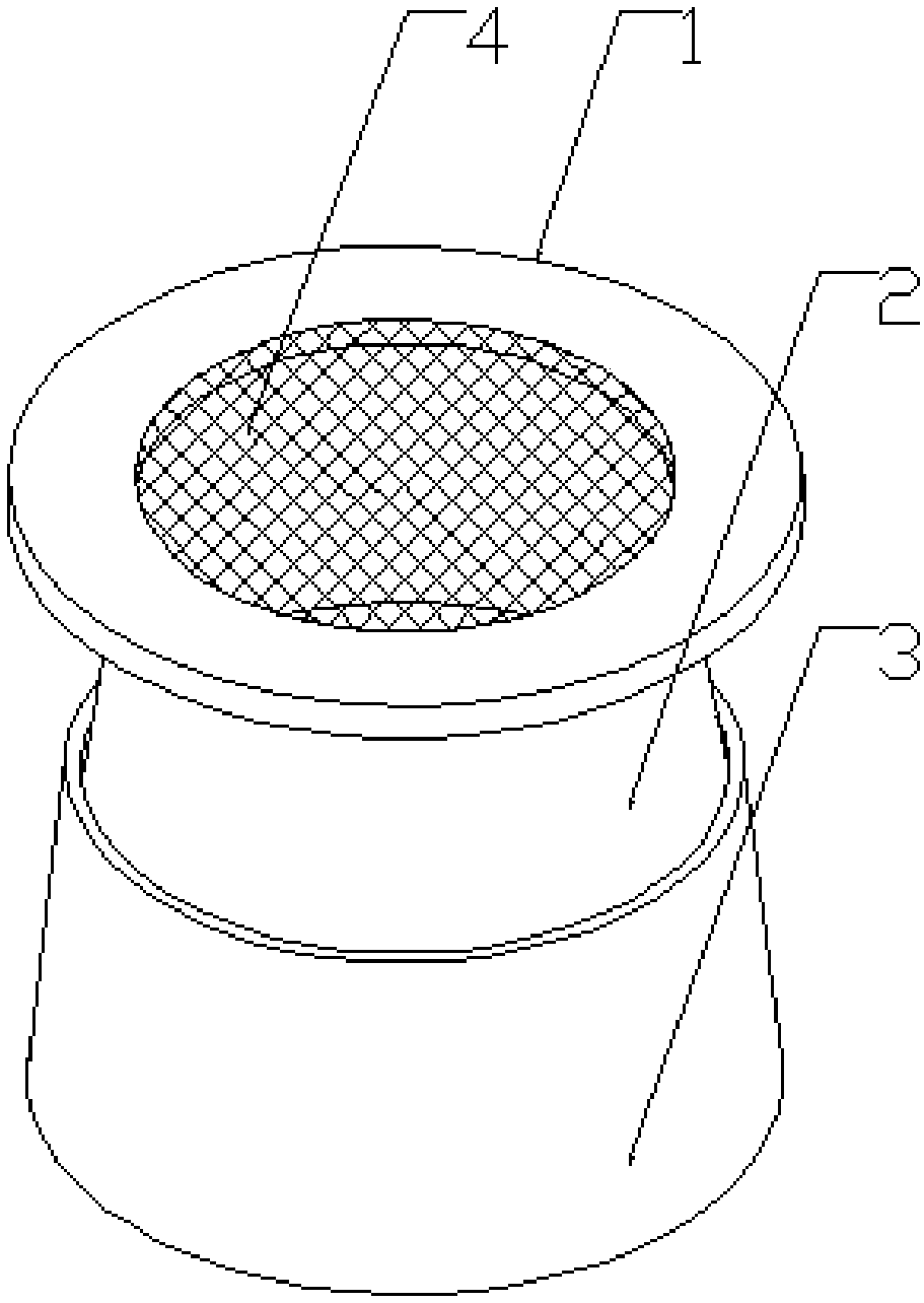
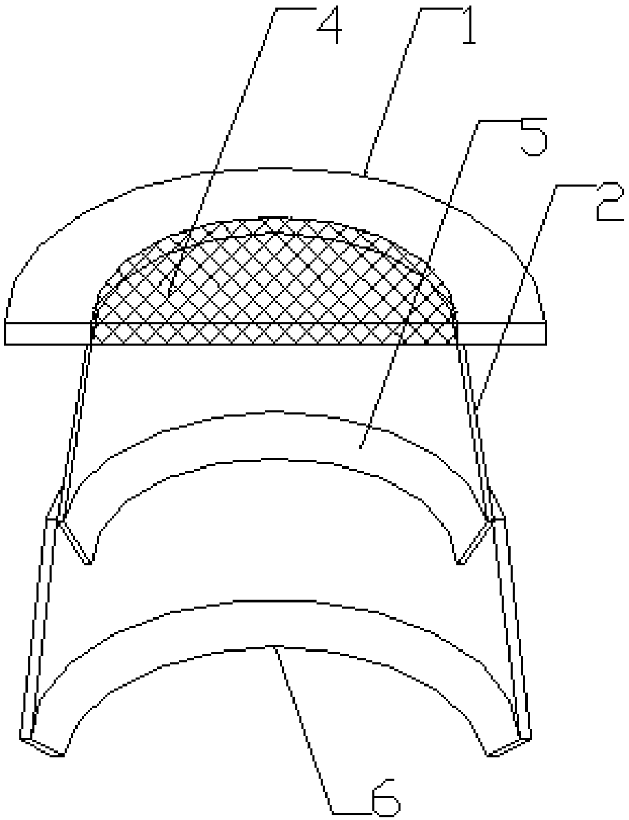
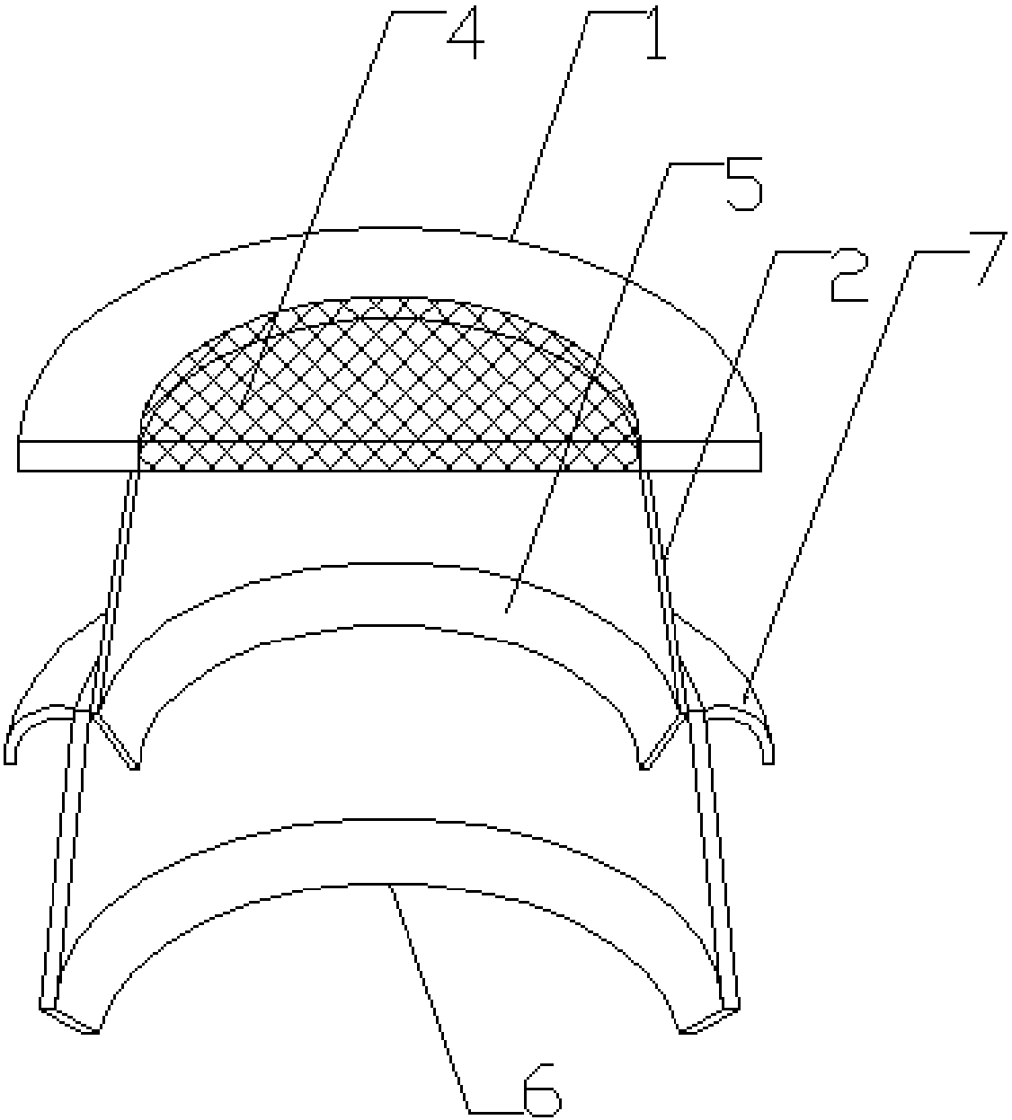
[0020] see figure 1 and figure 2 , this embodiment specifically provides a stacked dehydration structure for an exhaust gas absorption tower. The stacked dehydration structure for the exhaust gas absorption tower includes: an outer frame 1 of a ring structure, a hollow conical inner liner dehydration plate 2 is fixedly connected to the lower end surface of the outer frame 1, and the inner liner dehydration plate There is an outer lining dewatering plate 3 with a holl...


PUM


Abstract

The invention relates to a stacking type dewatering structure for a waste gas absorption tower. The stacking type dewatering structure comprises an external frame with an annular structure, wherein the lower end surface of the external frame is fixedly connected to an inner lining dewatering plate with a hollow cone-shaped structure, an outer lining dewatering plate with a hollow cone-shaped structure is sleeved and connected below the inner lining dewatering plate, the size of the opening on the outer lining dewatering plate is smaller than the size of the opening of the inner lining dewatering plate, the outer lining dewatering plate can move up and down relative to the inner lining dewatering plate along the axis of the outer lining dewatering plate, a first dewatering plate with a ventilation hole is arranged at the center of the external frame, and a circle of a first inner resistance edge and a circle of a second inner resistance edge are respectively arranged in the lower edgesof the inner lining dewatering plate and the outer lining dewatering plate. Compared to the structure in the prior art, the stacking type dewatering structure of the present invention can effectivelyachieve the dewatering effect and simplify the dewatering structure installation process.

Description

technical field [0001] The invention belongs to the technical field of environmental protection equipment, in particular to a stacked dehydration structure for an exhaust gas absorption tower. Background technique [0002] Exhaust gas treatment mainly refers to a purification method for industrial waste gas such as dust particles, flue gas smoke, odorous gas, and toxic and harmful gases generated in industrial places. [0003] The waste gas absorption tower is the main equipment for waste gas treatment. The waste gas absorption tower can dehydrate the waste gas. A dehydration plate will be installed in the waste gas absorption tower. The water vapor in the waste gas will condense on the dehydration plate to realize the dehydration of the waste gas. When passing through the dehydration plate, driven by the air flow of the exhaust gas, the water droplets on the dehydration plate in the exhaust gas absorption tower will have a wall-climbing phenomenon, and part of the water dro...

Claims


Application Information

Patent Timeline
IPC IPC(8): B01D53/18B01D53/26
CPCB01D53/18B01D53/265
Inventor 苏进平
Owner TIANJIN PULUOXIAN SCI & TECH CO LTD
Why Eureka
Try Eureka