
Automatic nut spot welding device

An automation device and nut technology, applied in auxiliary devices, welding equipment, welding equipment, etc., can solve the problems of difficulty in adapting to large-scale production, safety of nut hand being crushed, and low precision of dimensional tolerance, so as to eliminate finger crushing , to ensure stability, precision, and high production efficiency

Pending Publication Date: 2018-07-03
苏州盛贸汽车部件有限公司
View PDF0 Cites 4 Cited by
  • Summary
  • Abstract
  • Description
  • Claims
  • Application Information

AI Technical Summary

Problems solved by technology

[0002] In the existing continuous production, a large number of nuts are often spot-welded on the surface of parts. The current process is that the parts are placed on the lower electrode of the spot welding machine, and the nuts are manually placed in the jig positioning on the parts. The upper electrode presses the nuts and then Discharge, so that the nut is welded on the surface of the part, its shortcomings and defects are: first, there is a safety hazard of hand crushing when placing the nut manually; The tolerance is low and the yield rate is low; thirdly, manual manual spot welding of hand-held parts, due to high temperature or other factors during welding, the nut is unstable and easy to deform; fourthly, single spot welding consumes a lot of labor and the production efficiency is low. Difficult to adapt to mass production

Method used


Image

  • Automatic nut spot welding device
  • Automatic nut spot welding device
  • Automatic nut spot welding device

Examples


Embodiment Construction

[0034] The present invention will be described in further detail below in conjunction with the accompanying drawings.

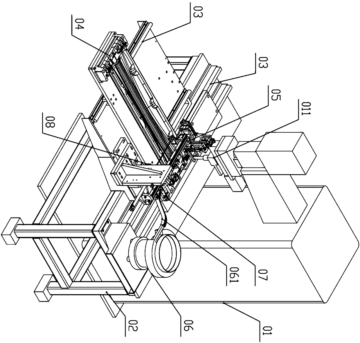
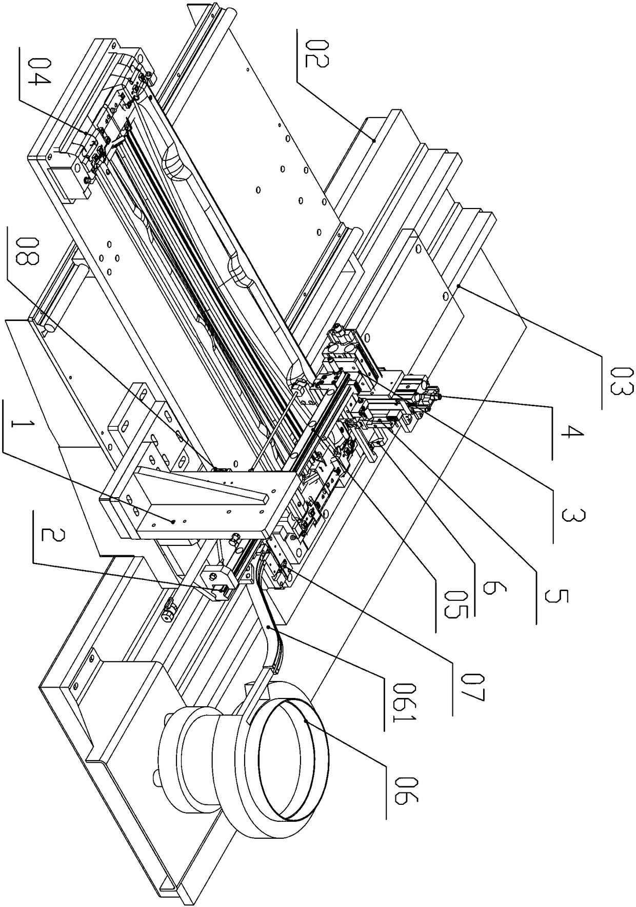
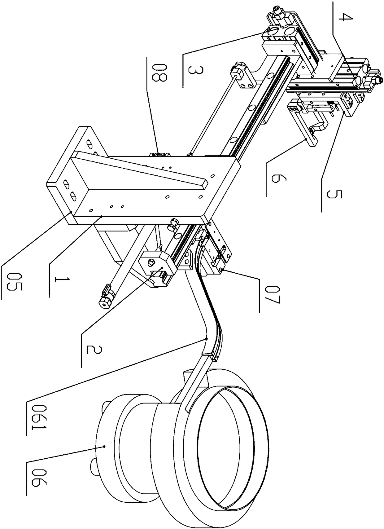
[0035] Figure 1 to Figure 10A nut spot welding automation device according to an embodiment of the present invention is schematically shown. As shown in the figure, the device includes a spot welder 01 and a workbench 02. The workbench 02 is located below the spot welder 01. The spot welder 01 has a vertically downward upper electrode welding head 011, and the workbench 02 is below the welding head 011. In the middle of the workbench 02, there is a moving part 03 that can move linearly. The moving part 03 is slidably connected to the workbench 02 through a slide rail slider. The upper side of the moving part 03 is fixed with a profiling positioning part 04. There are several positioning columns, and the product is fixed on the upper surface of the profiling positioning part 04, and the product is located under the welding head 011.

[0036] A vibration pla...


PUM


Abstract

The invention discloses an automatic nut spot welding device. The automatic nut spot welding device comprises a spot welding machine and a workbench, wherein the workbench is positioned below the spotwelding machine; a moving part is arranged at the middle of the workbench; a profiling positioning part is fixed on the upper side of the moving part; a product is fixed on the upper surface of the profiling positioning part; a nut delivery part, a vibration disk and a positioning part are fixed on one side of the workbench; the positioning part is positioned on the inner side of the vibration disk; a discharge end of the vibration disk is communicated with the positioning part through a feed guide rail, and is vertical to the direction of the feed guide rail; the positioning part is connected with a push part; a clamping point is arranged on the positioning part; the nut delivery part can move in three directions of X, Y and Z; and a chuck can clamp the nut on the clamping point and moveto the product welding end. The automatic nut spot welding device has the effects of automatic operation, high safety, accurate nut positioning, stable spot welding quality and high production efficiency.

Description

technical field [0001] The invention relates to a spot welding device, in particular to an automatic device for spot welding of nuts. Background technique [0002] In the existing continuous production, a large number of nuts are often spot-welded on the surface of parts. The current process is that the parts are placed on the lower electrode of the spot welding machine, and the nuts are manually placed in the jig positioning on the parts. The upper electrode presses the nuts and then Discharge, so that the nut is welded on the surface of the part, its shortcomings and defects are: first, there is a safety hazard of hand crushing when placing the nut manually; The tolerance is low and the yield rate is low; thirdly, manual manual spot welding of hand-held parts, due to high temperature or other factors during welding, the nut is unstable and easy to deform; fourthly, single spot welding consumes a lot of labor and the production efficiency is low. Difficult to adapt to mass...

Claims


Application Information

Patent Timeline
Patent Type & Authority Applications(China)
IPC IPC(8): B23K11/11B23K11/36B23K37/04
CPCB23K11/115B23K11/36B23K37/0435
Inventor 彭光荣
Owner 苏州盛贸汽车部件有限公司
Learn More