Combined cabinet with adjustable reagent frames

A combination cabinet and reagent rack technology, applied in the field of combination cabinets, can solve the problems of unfavorable adjustment space, non-adjustable, single function of the combination cabinet, etc., and achieve the effect of convenient use and simple structure

Inactive Publication Date: 2018-07-03
苏州市凯利勋实验室设备有限公司
View PDF7 Cites 3 Cited by
  • Summary
  • Abstract
  • Description
  • Claims
  • Application Information

AI Technical Summary

Problems solved by technology

[0003] Patent No. 201110172297.6 is a combination cabinet invention patent, which has developed a combination cabinet, which includes a unit plate and a deck. The unit plate is made of a regular rectangular frame wrapped with a sheet, and the deck is made of a cylindrical seat. The upper and lower sides of the well-shaped frame are integrally formed. The well-shaped frame is provided with four adjacent vertical well-shaped grooves. The diameter ribs are evenly divided into four fan-shaped grooves. The above well-shaped grooves are at the same vertical position as the diameter ribs in the lower seat body. However, most of the reagent racks in the existing combination cabinets are fixed and cannot be adjusted. Such combination cabinets are not conducive to reasonable adjustment of space. The function of the cabinet is also relatively simple. With the advancement of science and technology and the development of society, people have put forward higher requirements for the combination cabinet. Therefore, we have proposed a combination cabinet with an adjustable agent rack to solve the above problems.

Method used


Image

  • Combined cabinet with adjustable reagent frames
  • Combined cabinet with adjustable reagent frames
  • Combined cabinet with adjustable reagent frames

Examples


Embodiment Construction

[0022] The following will clearly and completely describe the technical solutions in the embodiments of the present invention with reference to the accompanying drawings in the embodiments of the present invention. Obviously, the described embodiments are only some, not all, embodiments of the present invention.

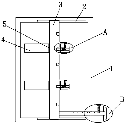
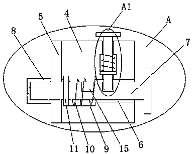
[0023] refer to Figure 1-5, a combination cabinet with an adjustable agent rack, including a combination cabinet body 1, the combination cabinet body 1 is a hollow structure, the top side and the bottom side inner wall of the combination cabinet body 1 are provided with chute 2, two chute 2 The same support rod 3 is slidably installed inside, and two reagent racks 4 are set on the support rod 3, and through holes 5 are opened on the two reagent racks 4, and the through holes 5 are slidably connected with the support rod 3. The inner wall of the side is provided with a slide bar through hole 6, and a slide bar 7 is slidably installed in the slide bar through hole 6, ...


PUM


Abstract

The invention discloses a combined cabinet with adjustable reagent frames. The combined cabinet comprises a combined cabinet body which is of a hollow structure, wherein sliding chutes are formed in the inner walls of the top side and bottom side of the combined cabinet body, one support rod is mounted in the two sliding chutes in a sliding manner and is sleeved with two reagent frames, through holes are formed in the two reagent frames and are connected with the support rod in a sliding manner, sliding rod through holes are formed in the inner walls of one sides of the through holes, slidingrods are mounted in the sliding rod through holes in a sliding manner, and two ends of the sliding rods extend outside the sliding rod through holes; and a first fixed slot is formed in one side, close to the sliding rod through hole, of the support rod, and one ends, close to the support rod, of the sliding rods are connected with the first fixed slot in a sliding manner. The combined cabinet issimple in structure and convenient to use, the reagent frames can be rapidly adjusted and fixed, the operation is easy, the time is saved, the functionality of the combined cabinet is increased, and the effective space in the combined cabinet is relatively reasonably utilized.

Description

technical field [0001] The invention relates to the technical field of combined cabinets, in particular to a combined cabinet with an adjustable agent rack. Background technique [0002] Reagent racks are generally installed on the tabletops of laboratory benches, experimental cabinets, and central experimental benches. The main function is to place glassware, test tubes, medicines, etc., to facilitate experimental operations. They are generally divided into wood reagent racks and steel wood reagent racks. [0003] Patent No. 201110172297.6 is a combination cabinet invention patent, which has developed a combination cabinet, which includes a unit plate and a deck. The unit plate is made of a regular rectangular frame wrapped with a sheet, and the deck is made of a cylindrical seat. The upper and lower sides of the well-shaped frame are integrally formed. The well-shaped frame is provided with four adjacent vertical well-shaped grooves. The diameter ribs are evenly divided i...

Claims


Application Information

Patent Timeline
Patent Type & Authority Applications(China)
IPC IPC(8): A47B81/02A47B57/20A47B96/02A47B97/00
CPCA47B81/02A47B57/20A47B96/028A47B97/00
Inventor 谢卫忠
Owner 苏州市凯利勋实验室设备有限公司
Why Eureka
Try Eureka