PCB production checking device

An inspection device and sliding installation technology, applied in the direction of measuring devices, workpiece clamping devices, instruments, etc., can solve the problems of unfavorable inspection effect, inconvenient PCB board shooting, no rotation and fixing mechanism, etc., so as to improve the inspection effect and facilitate shooting Check the effect

Pending Publication Date: 2020-11-06
AOSHIKANG TECH CO LTD
View PDF0 Cites 1 Cited by
  • Summary
  • Abstract
  • Description
  • Claims
  • Application Information

AI Technical Summary

Problems solved by technology

[0003] There are still many deficiencies in the traditional PCB board production inspection device. It does not have a four-way moving mechanism, which is not convenient for moving and adjusting the PCB board, which makes it inconvenient to take pictures of parts of the PCB board, and it does not have a rotation and fixing mechanism. As a result, it is inconvenient to adjust the angle of the PCB board, it is difficult to meet the actual shooting needs, and it is not conducive to improving the inspection effect

Method used


Image

  • PCB production checking device
  • PCB production checking device
  • PCB production checking device

Examples


no. 1 example

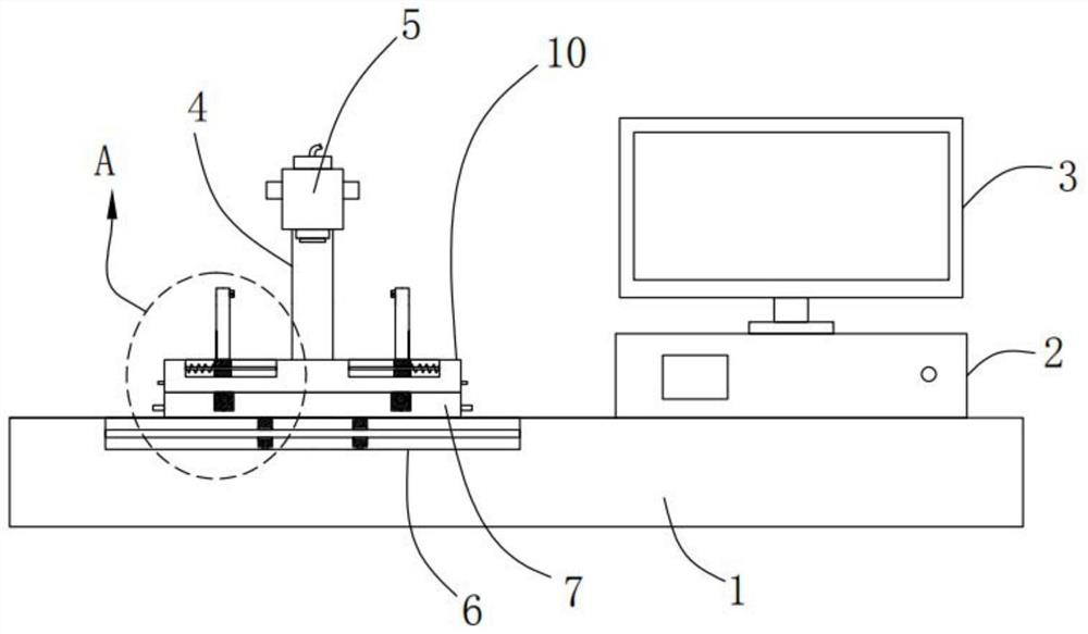
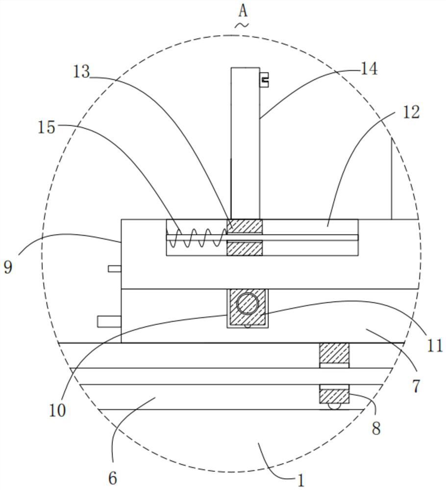
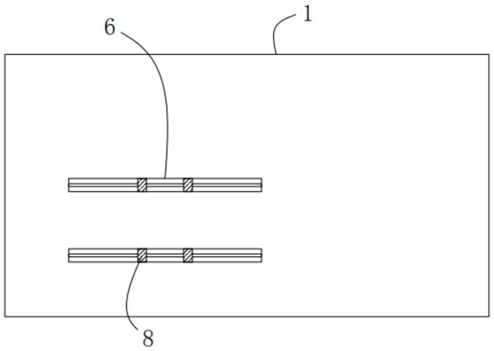
[0026] Please refer to Figure 1-3 , in the first embodiment of the present invention, the PCB production inspection device includes: an operating table 1; a host 2, the host 2 is fixedly installed on the top of the operating table 1; a display 3, the display 3 is fixedly installed on the top of the host 2 On the top, the display 3 is electrically connected to the host 2 through wires; the bracket 4 is fixedly installed on the top of the console 1; the camera 5 is fixedly installed on the bracket 4, and the camera 5 is connected to the host 2 through wires. Electrical connection; two first chute 6, the two first chute 6 are opened on the top of the console 1; a horizontal slide 7, the horizontal slide 7 is slidably installed on the top of the console 1; four The first slider 8, four first sliders 8 are respectively slidably installed in the corresponding first chute 6, the top of the first slider 8 is fixedly connected with the bottom of the horizontal slide 7; the longitudina...

no. 2 example

[0036] Based on the PCB production inspection device provided in the first embodiment of the present application, the second embodiment of the present application proposes another PCB production inspection device. The second embodiment is only a preferred mode of the first embodiment, and the implementation of the second embodiment will not affect the independent implementation of the first embodiment.

[0037] The second embodiment of the present invention will be further described below in conjunction with the drawings and implementation methods.

[0038] Please refer to Figure 4-5 , the PCB production inspection device also includes two rectangular through holes 16, and the two rectangular through holes 16 are opened on the corresponding splint 14 respectively, and a fourth slider 17 is slidably installed in the rectangular through holes 16, and the two fourth sliders One end of the block 17 that is far away from each other extends to the outside of the corresponding rect...


PUM


Abstract

The invention provides a PCB production checking device. The PCB production checking device comprises an operation table, a host, a display, a support, a camera, two first sliding grooves and a transverse sliding plate. The host is fixedly installed on the top of the operation table. The display is fixedly installed on the top of the host and is electrically connected with the host through a wire.The support is fixedly installed on the top of the operation table. The camera is fixedly installed on the support, and the camera is electrically connected with the host through a wire. The two first sliding grooves are formed in the top of the operation table. The transverse sliding plate is installed on the top of the operation table in a sliding manner. The PCB production checking device hasthe beneficial effects that use is convenient, operation is simple, four-direction moving and angle adjustment can be conducted on a PCB, local amplifying photographing can be conducted on the PCB conveniently, photographing with different angles can be conducted on the PCB conveniently, and the checking effect can be effectively improved.

Description

technical field [0001] The invention relates to the technical field of PCB board production, in particular to a PCB production inspection device. Background technique [0002] PCB board, also known as printed circuit board, is widely used in various electronic equipment, which brings great convenience to people's life and industrial production. During the production process, it is necessary to use inspection devices to check the soldering points to ensure Normal work, at present, the inspection of PCB boards is mainly carried out with the cooperation of high-definition CCD cameras and computers. [0003] There are still many deficiencies in the traditional PCB board production inspection device. It does not have a four-way moving mechanism, which is not convenient for moving and adjusting the PCB board, which makes it inconvenient to take pictures of parts of the PCB board, and it does not have a rotation and fixing mechanism. As a result, it is inconvenient to adjust the a...

Claims


Application Information

Patent Timeline
IPC IPC(8): B25B11/00G01D21/00
CPCB25B11/00G01D21/00
Inventor 肖仲波
Owner AOSHIKANG TECH CO LTD
Why Eureka
Try Eureka