Eureka AIR delivers breakthrough ideas for toughest innovation challenges, trusted by R&D personnel around the world.

Comb body of pet comb and pet comb

A comb and pet technology, applied in the field of pet combs, can solve the problems of unable to cut knotted hair, cutting unknotted hair, and stuck broken hair

Active Publication Date: 2018-07-03
NINGBO HONGDU MOSU CO LTD
View PDF9 Cites 9 Cited by
  • Summary
  • Abstract
  • Description
  • Claims
  • Application Information

AI Technical Summary

Problems solved by technology

[0005] The blades of the above-mentioned combs are located at the roots of the comb teeth. The comb has the following problems when grooming pets: 1. The blades at the root of the comb teeth may not touch the knotted hair that needs to be cut off, or because there are already broken hair clips At the root of the comb teeth, the resulting inability to cut off knotted hair
2. Unavoidable cutting of unknotted hairs

Method used


Image

  • Comb body of pet comb and pet comb
  • Comb body of pet comb and pet comb
  • Comb body of pet comb and pet comb

Examples


Embodiment 1

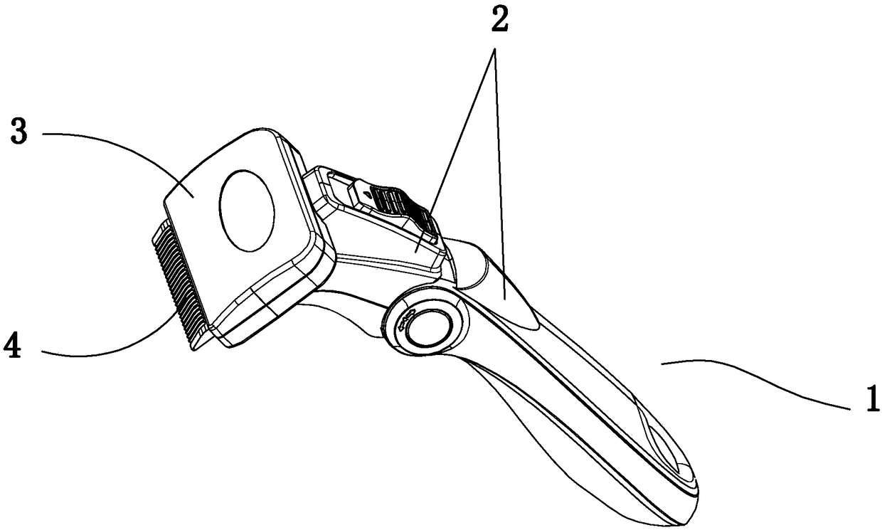
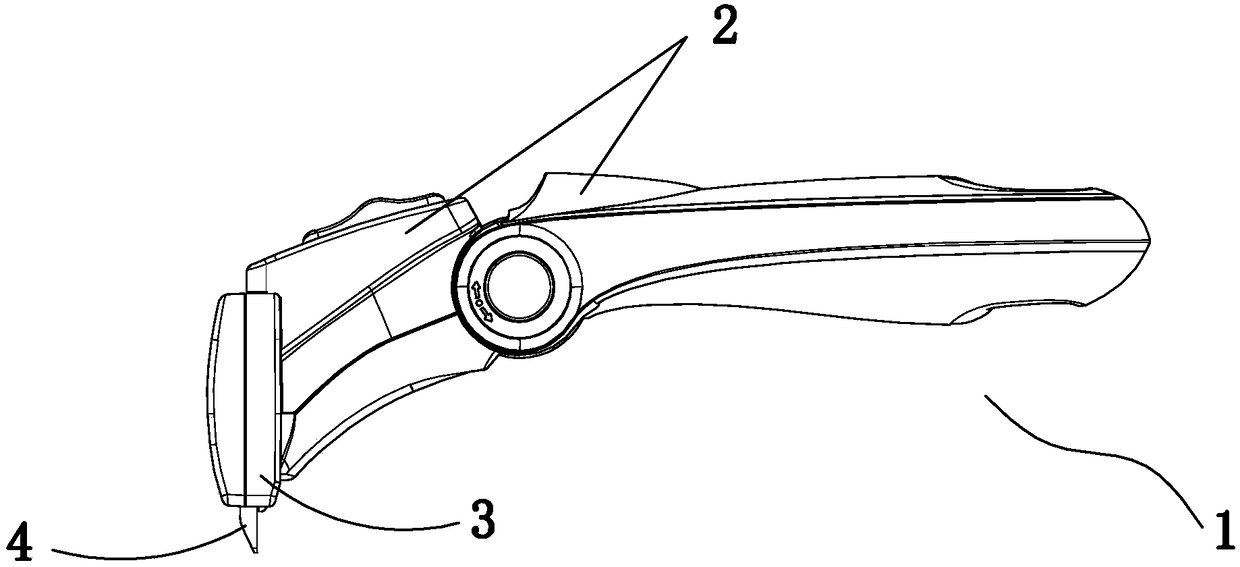
[0047] Embodiment one: if Figure 1 to Figure 7 As shown, the pet comb 1 includes an installation head 3 and a handle assembly 2, the installation head 3 is connected to the handle assembly 2, the comb body 4 is loaded into the installation head 3, and the back of the plate-shaped base 41 faces the comb comb. The movement direction of the hair is consistent, such as Figure 8 and Figure 9 As shown, the comb body 4 includes a plate-shaped base 41 and a row of strip-shaped comb teeth 42 of metal material at the front end of the plate-shaped base 41. Each strip-shaped comb tooth 42 is provided with a direction consistent with the direction of movement of the comb when combing hair. The cutting blade 421, when combing the hair of the pet, the moving direction of the comb is consistent with the direction of the blade, so that the knotted hair can be cut off easily. By applying a certain force, the connecting part of the hair can be cut off, and at the same time, the unknotted ha...

Embodiment 2

[0053] Embodiment two: if Figure 10 and Figure 11 As shown, other parts are basically the same as the embodiment, except that the shape of the cutting blade 421 is different. The cutting blade 421 of the second embodiment is a linear cutting blade, and the linear blade is positioned at the back of the comb body, that is, when combing hair with the comb. direction of motion is the same.

[0054] Such as Figure 10 As shown, the straight cutting edge is the middle edge of two symmetrical inclined surfaces. The smaller the angle between the two inclined surfaces, the sharper the cutting edge 421 is, otherwise, the blunter the cutting edge 421 is.

[0055] Such as Figure 11 , Figure 12 and Figure 20 As shown, the plate-shaped base 41 is made of plastic material, and the rear end of each strip-shaped comb tooth 42 has an assembly portion 44 , and the assembly portions 44 of the strip-shaped comb teeth 42 are independently assembled and fixed into the plastic material base...


PUM


Abstract

The invention discloses a pet comb and a comb body of the pet comb. The pet comb comprises a mounting head and a handle assembly, wherein the mounting head is connected to the handle assembly, the comb body is mounted in the mounting head, the backward orientation of a platy base is consistent to the moving direction of the comb combing hairs, the comb body comprises the platy base and a row of stripe-type comb teeth made from a metal material at the front end of the platy base, and a cutting edge, the orientation of which is consistent to the moving direction of the comb combing the hairs isarranged on each stripe-type comb tooth. The pet comb has the advantages that the cutting edges can be directly acted to knotted hairs; as the cutting edges are vertically acted to the hairs and an acting force of hand pulling is applied, the cutting edges can cut off the knotted hairs smoothly. According to the structure and orientation of the cutting edges, the situation which cannot be coped bythe cutting edges is avoided as relatively more knotted hairs are available. For the unknotted hairs, the comb teeth can comb the unknotted hairs, and the cutting edge structure can prevent the unknotted hairs from being cut off to the greatest extent.

Description

technical field [0001] The present invention relates to a pet grooming tool, in particular to a pet comb for removing loose or tangled hair from the fur of a pet. Background technique [0002] With the improvement of living standards, people's demand for pets is gradually increasing, and pets have become a part of our lives. [0003] The pet's fur will produce hair that falls off the skin, that is, the hair that is not attached to the skin. Now there are grooming tools on the market that are specially designed to clean up the shed hair or comb the hair neatly for pets. There is a hair scraper on the head of the grooming tool The comb is arranged with a row of comb teeth. However, the pet's hair often becomes knotted, and the above-mentioned traditional pet comb can be stuck by the knotted hair when combing the pet's hair. [0004] In order to solve the above-mentioned technical problem, the patent document of U.S. Patent No. US7077076B2 discloses a pet grooming tool, which...

Claims


Application Information

Patent Timeline
Patent Type & Authority Applications(China)
IPC IPC(8): A01K13/00
CPCA01K13/00A01K13/002
Inventor 张金春翟欣
Owner NINGBO HONGDU MOSU CO LTD
Why Eureka
Eureka Blog
Learn More