High-speed motor provided with variable air channel

A high-speed motor and air duct technology, applied in synchronous motors with stationary armatures and rotating magnets, mechanical equipment, electric components, etc., can solve the problems of high processing tolerance requirements, rising processing costs, and increasing the weight of the whole machine. Achieve the effect of reducing machining accuracy requirements, facilitating manufacturing and processing, and reducing the quality of the whole machine

Pending Publication Date: 2018-06-29
KUNSHAN YALIKANG ELECTRONICS TECH CO LTD
View PDF1 Cites 3 Cited by
  • Summary
  • Abstract
  • Description
  • Claims
  • Application Information

AI Technical Summary

Problems solved by technology

[0002] The complete motor with patent number CN201621361107.X includes: frame, rotor assembly (including magnet, bearing assembly, impeller and shaft), stator assembly (including C-shaped stator core and bobbin); the stator structure is relatively complex, and the inner wall of the frame The limited holes are used to support the rotor assembly, so the requirements for machining tolerances are relatively high, and the machining cost increases, and the frame is made of zinc material, which increases the weight of the whole machine

Method used


Image

  • High-speed motor provided with variable air channel
  • High-speed motor provided with variable air channel
  • High-speed motor provided with variable air channel

Examples


Embodiment Construction

[0018] In order to make the technical means, creative features, goals and effects achieved by the present invention easy to understand, the present invention will be further described below in conjunction with specific embodiments.

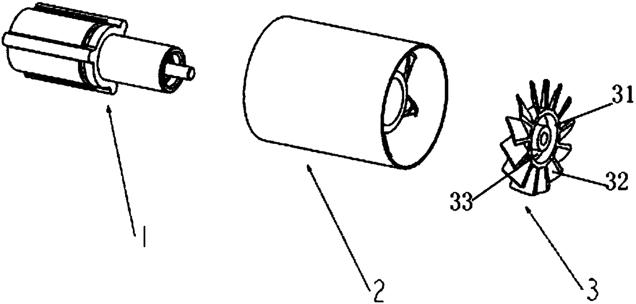
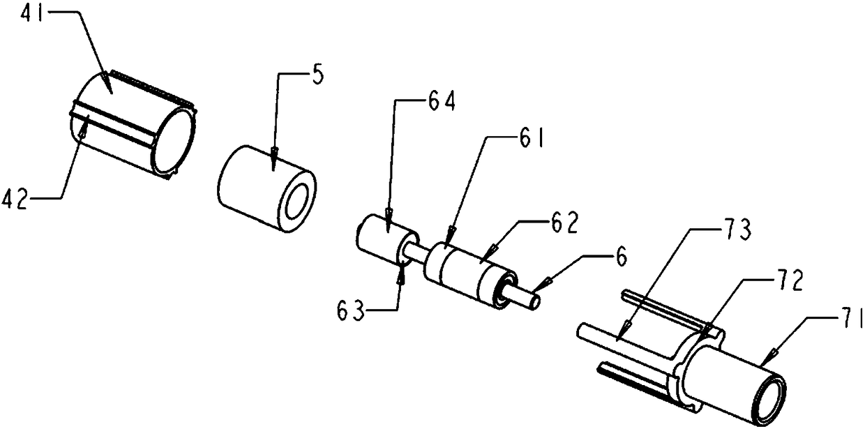
[0019] Such as Figure 1 to Figure 3 As shown, a variable air duct high-speed motor of the present invention includes a motor assembly 1, a hollow air duct 2 and an impeller 3, a hollow air duct 2 is provided outside the motor assembly 1, and one end of the motor assembly 1 is sleeved with the impeller 3; The motor assembly 1 is composed of a stator assembly, a rotor assembly and a casing 7; the casing 7 is used to connect and protect internal parts; the stator assembly includes a stator core 4 and a coil winding 5 arranged inside the stator core 4, and the rotor assembly includes There is a rotor core 6, and a bearing assembly is sleeved on the rotor core 6. The end of the rotor core 6 is sleeved with NdFeB permanent magnet salient poles 63 and o...


PUM


Abstract

The invention discloses a high-speed motor provided with variable air channel. The high-speed motor comprises a motor assembly, the hollow air channel and an impeller, wherein the hollow air channel is formed outside the motor assembly, and the impeller is in sleeve joint with one end of the motor assembly; the motor assembly comprises a stator assembly, a rotor assembly and a casing; the stator assembly comprises a stator core and a coil winding arranged in the stator core, the rotor assembly comprises a rotor core, a bearing assembly is connected onto the rotor core in a sleeving manner, anda Nb-Fe-B permanent magnet salient pole assembly is in sleeve joint with the tail end of the rotor core and is located on one side of the bearing assembly; the bearing assembly is connected to the front end in the casing, the rotor core is arranged in the casing through the bearing assembly, the stator core is connected into the tail end of the casing, the Nb-Fe-B permanent magnet salient pole assembly is accommodated in the stator iron core, and the coil winding is located between the Nb-Fe-B permanent magnet salient pole assembly and the stator core; the impeller is connected to one end ofthe rotor core. The high-speed motor is reasonable in design, simple in structure and convenient to manufacture, and cost is effectively reduced.

Description

technical field [0001] The invention relates to a fan, in particular to a variable air duct high-speed motor. Background technique [0002] The complete motor with patent number CN201621361107.X includes: frame, rotor assembly (including magnet, bearing assembly, impeller and shaft), stator assembly (including C-shaped stator core and bobbin); the stator structure is relatively complex, and the inner wall of the frame The limited holes are used to support the rotor assembly, so the requirements for machining tolerances are relatively high, and the machining cost increases, and the frame is made of zinc material, which increases the weight of the whole machine. Contents of the invention [0003] In order to overcome the above problems, the present invention provides a variable air duct high-speed motor. [0004] The technical solution of the present invention is to provide a variable air duct high-speed motor, which is characterized in that it includes a motor assembly, a ...

Claims


Application Information

Patent Timeline
Patent Type & Authority Applications(China)
IPC IPC(8): H02K21/14H02K9/06H02K5/24H02K5/04F04D25/08F04D29/32F04D29/52
CPCH02K21/14F04D25/08F04D29/325F04D29/329F04D29/522H02K5/04H02K5/24H02K9/06
Inventor 王敏王焕
Owner KUNSHAN YALIKANG ELECTRONICS TECH CO LTD
Why Eureka
Try Eureka