a rotating electromagnet

A technology of rotating electromagnets and armatures, which is applied in the field of rotating electromagnets, and can solve problems that affect the normal operation of rotating electromagnets and are easy to pull in.

Active Publication Date: 2020-04-28
HENAN AEROSPACE HYDRAULIC & PNEUMATIC TECH
View PDF6 Cites 0 Cited by
  • Summary
  • Abstract
  • Description
  • Claims
  • Application Information

AI Technical Summary

Problems solved by technology

[0004] The purpose of the present invention is to provide a rotating electromagnet to solve the technical problem that the axial arrangement of the armature and the stopper is easy to attract and affect the normal operation of the rotating electromagnet

Method used


Image

  • a rotating electromagnet
  • a rotating electromagnet
  • a rotating electromagnet

Examples


Embodiment Construction

[0022] Embodiments of the present invention will be further described below in conjunction with the accompanying drawings.

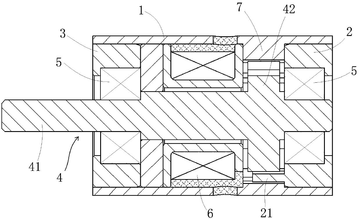
[0023] The specific embodiment of rotating electromagnet of the present invention, as figure 1 As shown, it includes a housing 1 , an upper end cover 2 , a lower end cover 3 , a rotor 4 , a coil assembly 6 and a stop iron 7 .

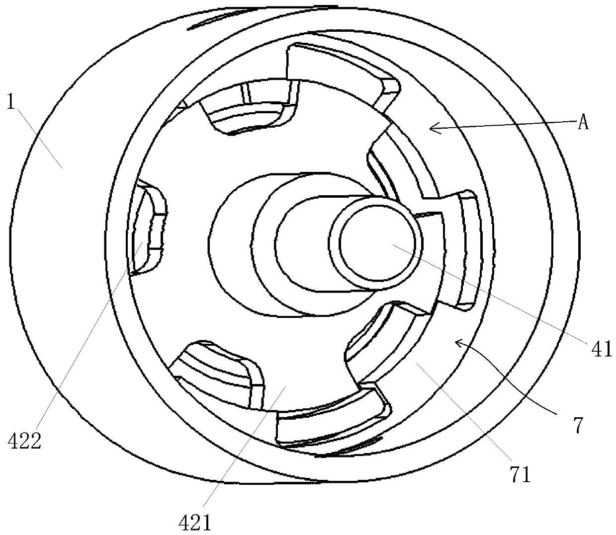
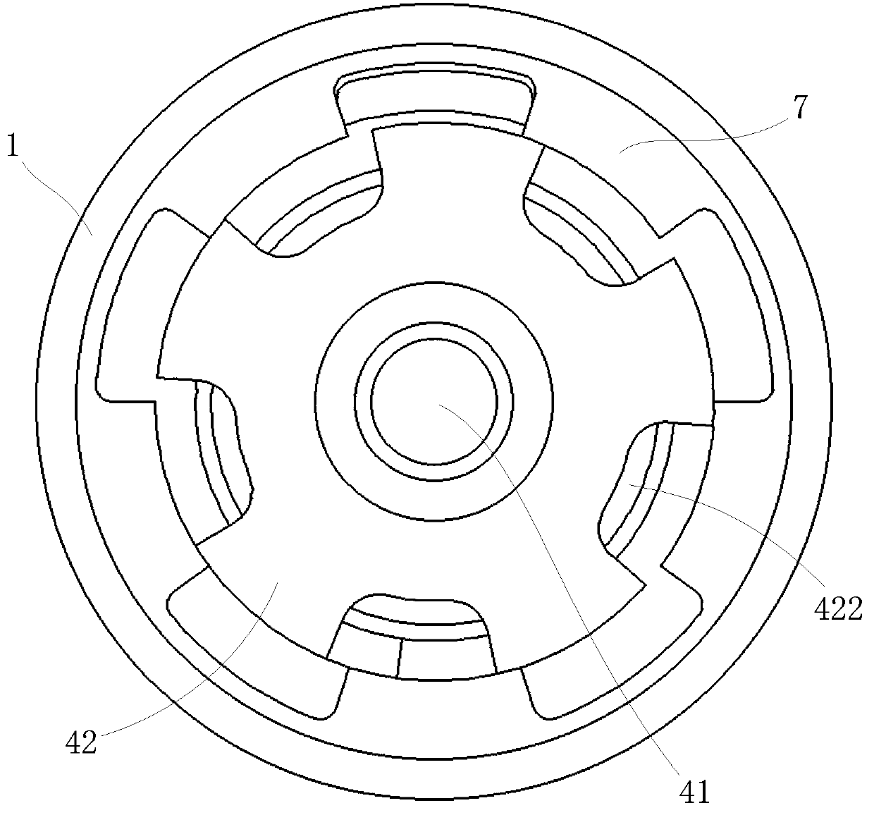
[0024] Such as Figure 4 As shown, the housing 1 is cylindrical, and an inwardly convex structure is provided inside the housing 1 near one end. The outer shell is made of magnetically conductive material. The structure is provided with internal teeth 71 arranged at intervals in the circumferential direction, and the internal convex structure and the internal teeth 71 together form the stopper 7 used in conjunction with the armature 42 . The outer peripheral surface of the internal teeth 71 is an arc surface, and the outer peripheral surfaces of the inner teeth 71 are located on the same peripheral surface.

[0025] Such as F...


PUM


Abstract

The invention relates to a rotating electromagnet. The rotating electromagnet comprises a housing and a rotating shaft which is rotatably mounted on the housing, an armature is fixedly arranged on therotating shaft, and a coil assembly is further mounted on the housing. The armature is sleeved with baffling iron, the baffling iron is fixed relative to the housing, and the outer circumference of the armature and the inner circumference of the baffling iron are correspondingly provided with an inner toothed structure and an outer toothed structure which are radially spaced apart and circumferentially staggered from each other at a motion starting position of the armature. The rotating electromagnet further comprises a limiting structure, the limiting structure is inserted into a tooth groove between two adjacent teeth of the inner toothed structure, and baffling limiting cooperation between the limiting structure and the teeth of the inner toothed structure is achieved at a left rotating extreme position and a right rotating extreme position of the armature through the two sides of the limiting structure respectively. The rotating electromagnet further includes an elastic componentwhich provides a restoring force for the armature in a powered off state. The attraction force of the baffling iron to the armature no longer has an axial component force, and therefore the problem inthe prior art that armatures and baffling iron are attracted together and correspondingly the normal operation of rotating electromagnets is affected can be avoided.

Description

technical field [0001] The invention relates to a rotating electromagnet. Background technique [0002] In many industrial production processes, it is often necessary to use a motor with limited rotation angle or an electromagnet with limited rotation angle (such as in the process of industrial automatic sorting). At present, there are two main types of common rotating electromagnets in China: one is a rotating electromagnet similar to a motor arrangement, and permanent magnets are arranged in the housing, and the stator armature windings are arranged at intervals along the circumferential direction on the teeth of the stator. For example, the rotating electromagnet disclosed in the utility model patent with the authorized announcement number CN203910404U relies on the superposition of the radial magnetic field generated by the coil wound on the stator and the axial magnetic field generated by the permanent magnet located in the moving iron core to generate electromagnetic r...

Claims


Application Information

Patent Timeline
Patent Type & Authority Patents(China)
IPC IPC(8): H01F7/14H01F7/127
CPCH01F7/127H01F7/14
Inventor 朱登魁路超任威陈浩赵芳陈志鹏康刘阳张亚娟张振炎孔宁宁
Owner HENAN AEROSPACE HYDRAULIC & PNEUMATIC TECH
Why Eureka
Try Eureka