Novel power cable equipment

A technology for power cables and equipment, applied in the field of new power cable equipment, can solve the problems of inconsistent soil layer density, easy uneven settlement of soil foundation, and tipping of poles, etc., to achieve convenient operation, improve leveling and beating effects, and improve work efficiency. Effect

Inactive Publication Date: 2018-06-29
广州酷汇电子科技有限公司
View PDF5 Cites 0 Cited by
  • Summary
  • Abstract
  • Description
  • Claims
  • Application Information

AI Technical Summary

Problems solved by technology

The traditional way is to use a shovel to tap the ground after backfilling the soil layer. This method is time-consuming and laborious, and the density of the soil layer is inconsistent. In case of heavy rain, the soil foundation is easy to settle unevenly, and it is easy to cause the pole to fall. At present, some automatic operating machines are single-hammer Piecework, low efficiency

Method used


Image

  • Novel power cable equipment
  • Novel power cable equipment
  • Novel power cable equipment

Examples


Embodiment Construction

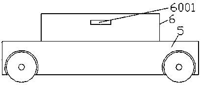
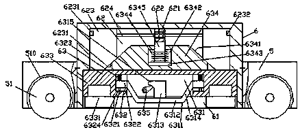
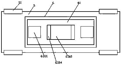
[0017] Such as figure 1 , figure 2 with image 3 As shown, a new type of power cable equipment of the present invention includes a base 5 and a soil conditioner 6 fixedly installed in the base 5, and the bottom surface of the soil conditioner 6 is provided with a first sinker 61, so The inner top wall of the first sinker 61 is communicated with a second sinker 62 extending upwards. The first sinker 61 is slidingly fitted with a lifting block 63 connected to the top of the lifting block 63. A push block 634 that penetrates into the second sinking groove 62 and is connected by sliding fit is fixed, and the left and right sides of the push block 634 are correspondingly provided with a first inclined surface 6341, and the opposite sides of the push block 634 are The inner top wall of the second sinking groove 62 is fixed with a convex end block 621, and the bottom surface of the lifting and sliding block 63 is provided with a third sinking groove 631, and the left and right sid...


PUM


Abstract

The invention discloses novel power cable equipment. The novel power cable equipment comprises a base and a soil preparation machine fixedly installed in the base. A first sinking tank is formed in the bottom surface of the soil preparation machine. A second sinking tank extending upwards is arranged on the top wall inside the first sinking tank in a communicating mode. A rising and falling sliding block is connected inside the first sinking tank in a sliding fit mode. A pushing block extending into the second sinking tank and connected with the second sinking tank in a sliding fit mode is fixedly arranged at the top of the rising and falling sliding block. First inclined surfaces are correspondingly arranged on the left side and the right side of the pushing block. A convex end block is fixedly arranged at the position, opposite to the top of the pushing block, of the top wall inside the second sinking tank. A third sinking tank is arranged in the bottom surface of the rising and falling sliding block. Rotary movement connecting sinking tanks extending front and back are correspondingly arranged on the left side and the right side of the third sinking tank. A hammer head is connected in each rotary movement connecting sinking tank in a rotary movement fit mode. A beating device is connected inside the third sinking tank in a matched mode. The novel power cable equipment is simple in structure, is convenient to operate, reinforces the firmness of beating of a soil layer, and improves the work efficiency of the beating work of the soil layer.

Description

technical field [0001] The invention relates to the technical field of power cables, in particular to a new type of power cable equipment. Background technique [0002] In order to improve the urban and rural power distribution, it is necessary to increase the laying of the power line network in a reasonable and orderly manner. Before erecting the cables, it is necessary to dig a hole in the bottom surface to fix the cable rack. The stability of the cable rack is directly related to the safety and quality of the line erection. . The traditional way is to use a shovel to tap the ground after backfilling the soil layer. This method is time-consuming and laborious, and the density of the soil layer is inconsistent. In case of heavy rain, the soil foundation is prone to uneven settlement, which can easily cause the pole to fall. At present, some automatic operating machines are single-hammer Piece work, low efficiency. Contents of the invention [0003] The technical problem...

Claims


Application Information

Patent Timeline
IPC IPC(8): E02F3/76E02F3/84
CPCE02F3/76E02F3/84
Inventor 吴波挺
Owner 广州酷汇电子科技有限公司
Why Eureka
Try Eureka