Spinning device and parallel spinning method with the same
A parallel spinning and spinning technology, which is applied to spinning machines, textiles, papermaking, and drafting equipment, can solve the problems of high production management costs, large energy consumption, and complex structures, and achieve low maintenance and management costs. Can reduce and improve the effect of yarn quality
- Summary
- Abstract
- Description
- Claims
- Application Information
AI Technical Summary
Problems solved by technology
Method used
Image
Examples
Embodiment 1
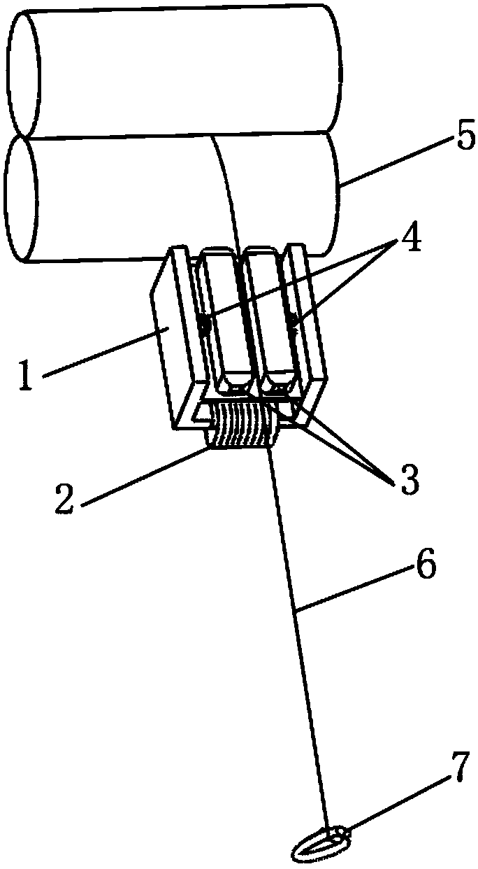
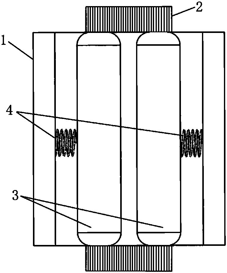
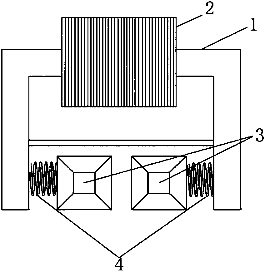
[0057] In a kind of spinning device of the present invention, the strands pass through the yarn guide hook after being output from the front roller jaw, such as figure 1 As shown, a spinning oscillator is provided between the front roller and the yarn guide hook, and the spinning oscillator is composed of a pair of vibrating accumulating rollers 3, a resonant spring 4, a magnetic core 1, a coil 2, a power supply, a front roller 5 and a yarn guide Hook 7 constitutes. The ratio of the distance between the spinning oscillator to the nip of the front roller and the distance between the spinning oscillator and the yarn guide hook is 1 / 30, and the magnetic core 1 is a rectangular groove structure consisting of opposite side walls and a bottom wall , the coil 2 is wound on the bottom wall of the magnetic core 1 and connected to the power supply; a pair of vibrating gathering rollers 3 are magnetically conductive materials and are respectively connected to the inner surface of the sid...
Embodiment 2
[0061] A kind of spinning device of the present invention, structural composition is basically consistent with embodiment 1, the difference is that the ratio of the distance between the spinning oscillator to the nip of the front roller and the distance between the spinning oscillator and the yarn guide hook is 1 / 5, The excitation frequency of the magnetic core 1 is 60Hz, the natural frequency of a pair of vibrating gathering rollers 3 and resonance spring 4 is 50Hz, and the elongation rate of the resonance spring 4 is 30%. When the resonance spring 4 is in the original length state, the two gathering rollers The angle between the axial directions is 10°, the minimum distance between a pair of vibrating gathering rollers 3 along the vibration direction is 2 mm, the minimum distance between a pair of vibrating gathering rollers 3 and the bottom wall of the magnetic core 1 is 9 mm, and a pair of vibrating gathering rollers 3 has a minimum distance of 9 mm. The collecting rollers ...
Embodiment 3
[0065] A kind of spinning device of the present invention, the structural composition and embodiment 1 are basically consistent, the difference is that the ratio of the distance between the spinning oscillator to the nip of the front roller and the distance between the spinning oscillator and the yarn guide hook is 1 / 10, The excitation frequency of the magnetic core 1 is 20Hz, the natural frequency of the vibrating gathering roller 3 and the resonant spring 4 is 20Hz, the elongation of the resonant spring 4 is 10%, and when the resonant spring 4 is in the original long state, the two gathering rollers axially The angle between the two vibrating gathering rollers 3 is 2mm along the vibration direction, and the minimum distance between each vibrating gathering roller 3 and the bottom wall of the magnetic core 1 is 5mm. Each vibrating gathering roller 3 It is a cylindrical gathering roller perpendicular to the bottom wall of the magnetic core 1, and a plurality of vibrating gather...
PUM
| Property | Measurement | Unit |
|---|---|---|
| Resonant frequency | aaaaa | aaaaa |
| surface roughness | aaaaa | aaaaa |
| elongation | aaaaa | aaaaa |
Abstract
Description
Claims
Application Information
 - R&D
- Intellectual Property
- Life Sciences
- Materials
- Tech Scout
- Unparalleled Data Quality
- Higher Quality Content
- 60% Fewer Hallucinations
Browse by: Latest US Patents, China's latest patents, Technical Efficacy Thesaurus, Application Domain, Technology Topic, Popular Technical Reports.
© 2025 PatSnap. All rights reserved.Legal|Privacy policy|Modern Slavery Act Transparency Statement|Sitemap|About US| Contact US: help@patsnap.com


