Inflatable winding chuck of slitting machine

An inflatable and slitting machine technology, applied in the field of rolling fixtures, can solve the problems of manufacturing cost, high maintenance cost, large overall structure volume, increased control cost, etc., to reduce energy consumption, simple overall structure, and save manufacturing Effect

Active Publication Date: 2018-06-29
杭州大华工控技术有限公司
View PDF6 Cites 7 Cited by
  • Summary
  • Abstract
  • Description
  • Claims
  • Application Information

AI Technical Summary

Problems solved by technology

[0002] When winding and unwinding the coil, the air-inflating chuck is usually used. After inflating, the surface protrusions press the inner surface of the coil, and the protrusions on the deflated surface retract to loosen the inner surface of the coil. For example, it is called " The disclosed technology shown in "Mechanical Inflatable Chuck" (Notice No.: CN205739599U), the disclosed technology includes a housing, a number of key grooves are provided on the side wall of the housing, key bars are provided in the key grooves, and key bars along the housing are provided in the housing. Axially moving linkage block, the linkage block has a frustum-shaped structure, and the axial movement of the linkage block squeezes the key bar and converts it into the radial movement of the key bar; the disclosed technology has the following disadvantages: a single cylinder structure is adopted, and two pairs of bearings are used respectively. Connected with the linkage block and the shell, the structure is complex, and the manufacturing cost and maintenance cost are high; the overall structure is bulky, and it is difficult to apply when the inner hole of the cylinder after winding is small; especially, the pressure maintaining of the cylinder depends on the external The pneumatic system increases the cost of control, and the external pneumatic system is always in working condition during the pressure maintaining process, which not only affects the service life, but also is not conducive to energy saving

Method used


Image

  • Inflatable winding chuck of slitting machine

Examples


Embodiment

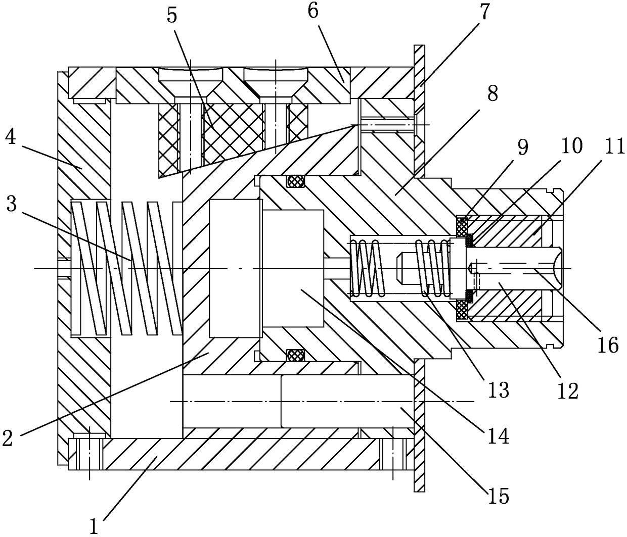
[0014] Embodiment: The air-expandable rewinding chuck of the slitting machine of the present invention, as attached figure 1 As shown, it includes an outer casing 1, an end shaft 8, a steel core 2 and several tension blocks 6.

[0015] The outer casing 1 is a circular cylindrical structure with a cavity inside, the left end is closed, and the right end is open;

[0016] The end shaft 8 is located at the open end of the outer casing 1; the end shaft 8 partly extends into the outer casing 1, and the extension end is a stepped structure with end shrinkage, and the guide shaft 14 is axially arranged on the side wall of the step portion; the end shaft 8 is axially Set three-stage stepped holes, the diameters of the three stages are gradually smaller, the diameter of the tail section connecting the cavity 14 is the smallest, the air nozzle 12 is set in the middle hole, the washer 9 and the locking sleeve 11 of the compression washer 9 are set in the right hole, and the locking sleev...


PUM


Abstract

The invention relates to an inflatable winding chuck of a slitting machine, comprising: a jacket; an end shaft partially extended into the jacket, wherein the extension end is in shrinking-end steppedstructure, the end shaft is axially provided with a three-segment stepped hole, a nozzle / gasket and a lock collar / O-shaped ring are arranged in the three-segment stepped hole, the outer edge of the O-shaped ring is abutted to the corners of the peripheral wall of a bore of the gasket, the nozzle is provided with a first spring at its left shaft segment, a right shaft segment of the nozzle is in sliding fit with the lock collar, the right shaft segment is provided with an intake passage, an inlet of the intake passage is positioned at the end of the right shaft segment, and an outlet of the intake passage is positioned on the outer periphery on the right of the O-shaped ring; a steel core, wherein the middle of the right end of the steel core is provided with a groove, the left end of thesteel core is provided with a second spring, and the outer peripheral face of the spring end is provided with a plurality of slants; and a plurality of expansion blocks. A cavity is arranged between the bottom of the groove of the steel core and the end face of the end shaft and is communicated with a left part of the three-segment stepped hole. After inflating, pressure can be automatically held;overall size is greatly reduced, the radial size of the whole structure can be reduced particularly, and the need for winding barrels having small inner diameter is met.

Description

technical field [0001] The invention relates to a rolling fixture, in particular to an inflatable rolling chuck of a slitting machine. Background technique [0002] When winding and unwinding the coil, the air-inflating chuck is usually used. After inflating, the surface protrusions press the inner surface of the coil, and the protrusions on the deflated surface retract to loosen the inner surface of the coil. For example, it is called " The disclosed technology shown in "Mechanical Inflatable Chuck" (Notice No.: CN205739599U), the disclosed technology includes a housing, a number of key grooves are provided on the side wall of the housing, key bars are provided in the key grooves, and key bars along the housing are provided in the housing. Axially moving linkage block, the linkage block has a frustum-shaped structure, and the axial movement of the linkage block squeezes the key bar and converts it into the radial movement of the key bar; the disclosed technology has the fol...

Claims


Application Information

Patent Timeline
IPC IPC(8): B65H75/24
CPCB65H75/243B65H2701/50
Inventor 许炯
Owner 杭州大华工控技术有限公司
Why Eureka
Try Eureka