
Balance car

A balancing car and tire technology, applied in the field of balancing cars, can solve problems such as poor operating sensitivity, high operating difficulty, and danger-prone, and achieve the effects of reducing operating difficulty, convenient control, and improving operating sensitivity

Pending Publication Date: 2018-06-29
YINGFANDI BEIJING SCI & TECH LTD
View PDF8 Cites 6 Cited by
  • Summary
  • Abstract
  • Description
  • Claims
  • Application Information

AI Technical Summary

Problems solved by technology

[0003] However, the current self-balancing car has the following disadvantages in the operation process: during the turning process of the unicycle self-balancing car, the user needs to adjust the left and right inclination of the car body by controlling the pedaling force of the left and right tires to turn, and the operation is difficult. , prone to danger; during the turning process of the two-wheel balance car, the user needs to control the swing of the waist and the control of the steering handle to control the car body to turn, and the operation sensitivity is poor

Method used

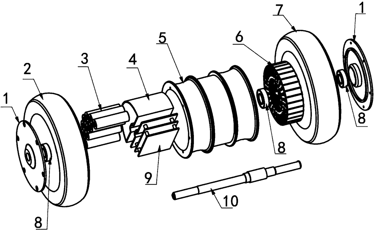
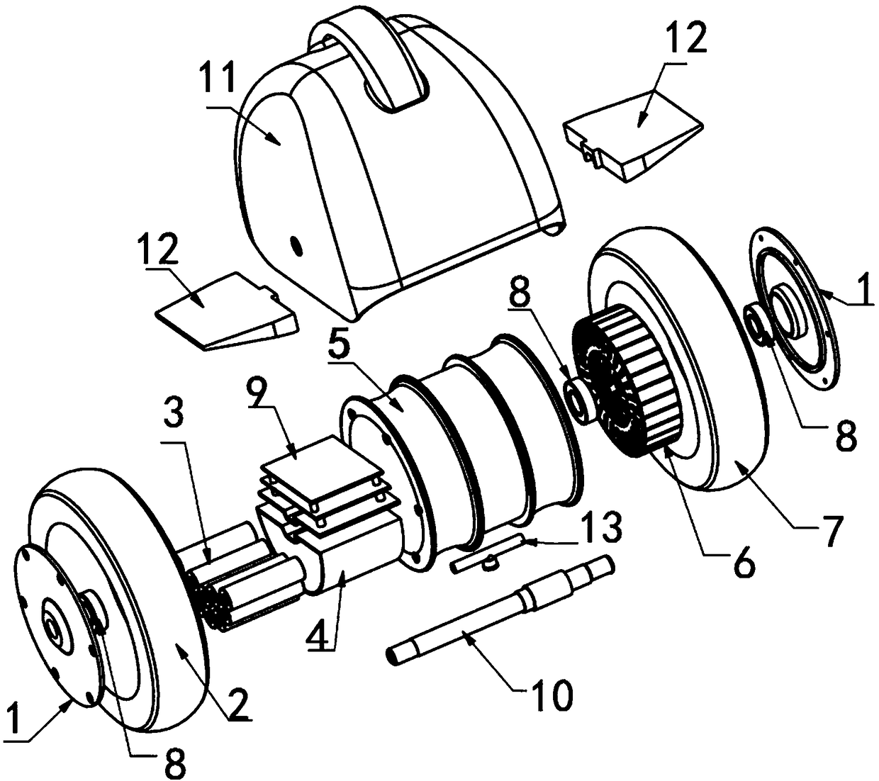

Image

  • Balance car
  • Balance car
  • Balance car

Examples


Embodiment 1

[0037] Combine figure 1 , figure 2 , image 3 As shown, the embodiment of the present invention provides a balance car, which may include a power supply, a control circuit, a hub motor, and pneumatic tires. The power supply is used to supply power to the balance car, and the control circuit is used to control the operation of the hub motor; the hub motor includes a hub rotor 5 The motor stator 6 arranged in the hub rotor 5; the pneumatic tire is sleeved on the outside of the hub rotor 5; through the above-mentioned power supply setting, the necessary power can be provided for the operation of the internal components of the balance car, through the above-mentioned control circuit setting , Can effectively realize the effective control operation of the in-wheel motor operation.

[0038] In this embodiment, the above-mentioned pneumatic tire includes a left tire 2 and a right tire 7. The left tire 2 and the right tire 7 are respectively sleeved on the left and right sides of the hub...

Embodiment 2

[0051] The essential difference between the second embodiment and the first embodiment is that the connection mode of the housing is different.

[0052] In the second embodiment provided by the present invention, the two ends of the motor shaft are respectively connected to the two side walls of the housing, and the foot pedals can be directly arranged on both sides of the housing without connecting with the motor shaft; between the motor shaft and the housing The preferred connection method can also achieve the stability of the connection between the housing and the motor shaft.

[0053] In addition, in this embodiment, the above-mentioned power supply can be located outside the hub rotor, and the power supply also includes a battery box and a battery pack; the above-mentioned control circuit can also include a PCB main control board, which can also be connected to the battery box and set together Outside the hub rotor.

[0054] Compared with the prior art, the present invention ca...


PUM


Abstract

The invention discloses a balance car, comprising a power supply, a control circuit, a hub motor and pneumatic tires. The power supply is used for supplying power to the balance car. The control circuit is used for controlling the operation of the hub motor. The hub motor comprises a hub rotor and a motor stator arranged in the hub rotor. The outer side of the hub rotor is sleeved with the pneumatic tires. The pneumatic tires comprise a left tire and a right tire, the left tire and the right tire are respectively arranged on the left and right sides of the hub rotor in a sleeving manner, and an inner cavity of the left tire communicates with an inner cavity of the right tire. The balance car can be applied to the technical field of vehicles. The balance car can effectively overcome the defects in the prior art, can realize convenient control over the turning operation through optimization and improvement of the pneumatic tires, can effectively improve the operation sensitivity, and caneffectively reduce the difficulty in operation.

Description

Technical field [0001] This application relates to, but is not limited to, the technical field of vehicles, especially a balance vehicle. Background technique [0002] In the prior art, balance cars are also called somatosensory cars, thinking cars, and camera cars. There are mainly two types of uni-wheels and two-wheels in the market; its operating principle is mainly based on a basic principle called "dynamic stability", which uses the gyroscope and acceleration sensor inside the car body to detect the body attitude Change and use the servo control system to accurately drive the motor to make corresponding adjustments to maintain the balance of the system. [0003] However, the current balance scooter has the following shortcomings during the operation process: during the turning process of the unicycle balance scooter, the user needs to adjust the left and right tilt of the car body to turn by controlling the pedaling force of the left and right feet of the tire, which is diffi...

Claims


Application Information

Patent Timeline
IPC IPC(8): B62K3/00B60C23/00
CPCB60C23/00B60C2200/10
Inventor 石崇阳
Owner YINGFANDI BEIJING SCI & TECH LTD
Learn More