
Quick bearing disassembly device

A bearing and U-shaped technology, which is applied in the field of rapid disassembly of bearings, can solve the problems of small number of claws, damage to the contact end surface of the bearing, and outward slipping of claws, etc.

Inactive Publication Date: 2018-06-29
AECC SICHUAN GAS TURBINE RES INST
View PDF1 Cites 2 Cited by
  • Summary
  • Abstract
  • Description
  • Claims
  • Application Information

AI Technical Summary

Problems solved by technology

Although the puller is widely used, there are certain defects in the process of use, such as the small number of claws, uneven force on the bearing; the angle of the hook at the end of the claw is constant, and the contact end surface with the bearing is often not face-to-face when pulling. Contact, the contact stress is large, so it will cause certain damage to the contact end surface of the bearing; when the claw is used to pull the bearing, generally the radial direction of the claw is not constrained, and when the pulling force is relatively large, it is easy to cause the claw to slip outward and cause damage to the bearing. Damage to bearing contact faces

Method used


Image

  • Quick bearing disassembly device
  • Quick bearing disassembly device

Examples


Embodiment Construction

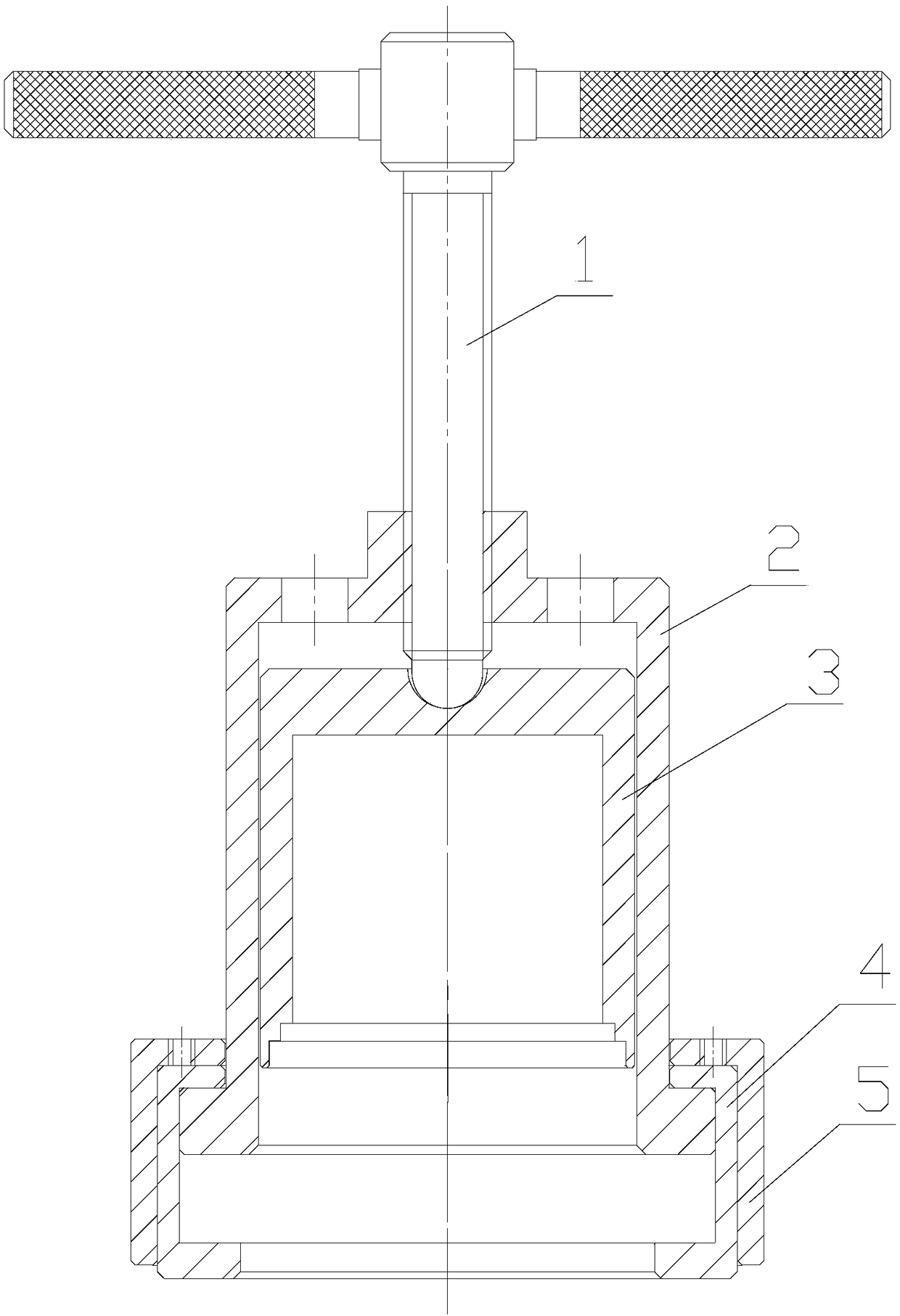
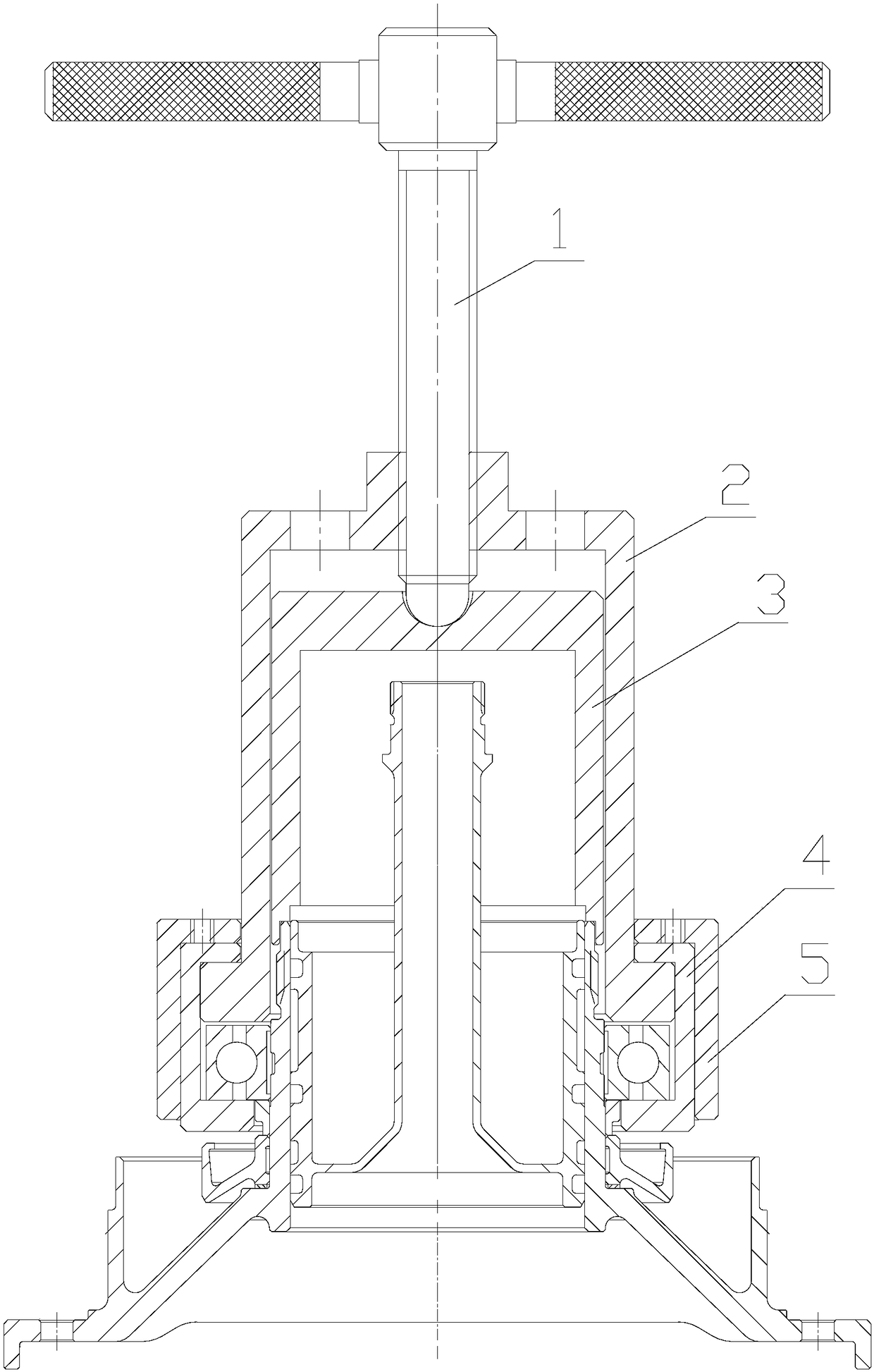
[0014] The present invention will be described in further detail below in conjunction with the accompanying drawings of the description, please refer to figure 1 , figure 2 .

[0015] figure 2 Shown is a diagram of the use method of a quick disassembly bearing device of the present invention. The device comprises a push rod 1, a puller plate 2, a spacer 3, a U-shaped half-pull ring 4, and a pull ring clamp ring 5. The method of use is to first place the spacer 3 on the end face of the rotor shaft journal, insert the puller 2 onto the block 3, and then clamp the U-shaped half-open ring 4 between the lower end face of the bearing and the upper end face of the puller 2, Then use the puller clamp ring 5 to be inserted into the U-shaped half-drawn ring 4 to play the role of tightening the U-shaped half-drawn ring 4, and finally the push rod 1 is screwed into the threaded hole of the puller 2, and kept Rotating at a constant speed, along with the tightening of the ejector rod ...


PUM


Abstract

The invention belongs to the technical field of aeroengine assembly and particularly relates to a quick bearing disassembly device as shown in a drawing 1. The quick bearing disassembly device is simple in structure and convenient to operate. A bearing is pulled after being clamped by U-shaped open half pulling rings and is uniform in peripheral stress, and high contact stress is avoided due to surface-to-surface contact of contact end faces; the U-shaped open half pulling rings are tightly hooped by a pulling ring hoop and prevented from expanding outwards in a bearing pulling process, and slipping like pulling claws can be avoided. Therefore, the quick bearing disassembly device has advantages of high reliability, disassembly quality stability, high efficiency and high popularization andapplication value.

Description

technical field [0001] The invention belongs to the technical field of aero-engine assembly, and in particular relates to a device for rapidly decomposing a bearing. Background technique [0002] During the assembly and disassembly process of the aero-engine, the bearings are often disassembled according to the needs. The main bearings of the aero-engine are generally installed on the journal of the engine, such as the front journal of the compressor or the rear journal of the turbine. Commonly used bearing disassembly methods include pressure unloading method and pull-off method, but because of the characteristics of aero-engine journals, it is generally not suitable to use the pressure-unloading method for disassembly, and the pull-off method is usually used. The most commonly used method of pulling and unloading is the puller, which can be divided into two claws, three claws, etc. according to the number of claws. Because of its simple structure and certain adjustability...

Claims


Application Information

Patent Timeline
Patent Type & Authority Applications(China)
IPC IPC(8): B25B27/06
CPCB25B27/062
Inventor 白彦徐广庆雷琼先李冠一
Owner AECC SICHUAN GAS TURBINE RES INST
Learn More