
Coloring agent preparation machine for textile dyeing

The technology of dyeing agent and preparation machine is applied in the field of dyeing agent preparation machine for textile dyeing, which can solve the problems of low mixing efficiency, uneven mixing, complicated operation, etc., and achieve the effect of speeding up the mixing

Inactive Publication Date: 2018-06-26
孙冲
View PDF2 Cites 5 Cited by
  • Summary
  • Abstract
  • Description
  • Claims
  • Application Information

AI Technical Summary

Problems solved by technology

[0006] In order to overcome the disadvantages of low mixing efficiency, uneven mixing and complicated operation in existing dyeing agent mixing preparation machines, the technical problem to be solved by the present invention is to provide a textile dyeing machine with high mixing efficiency, relatively uniform mixing and simple operation. dye preparation machine

Method used


Image

  • Coloring agent preparation machine for textile dyeing
  • Coloring agent preparation machine for textile dyeing
  • Coloring agent preparation machine for textile dyeing

Examples


Embodiment 1

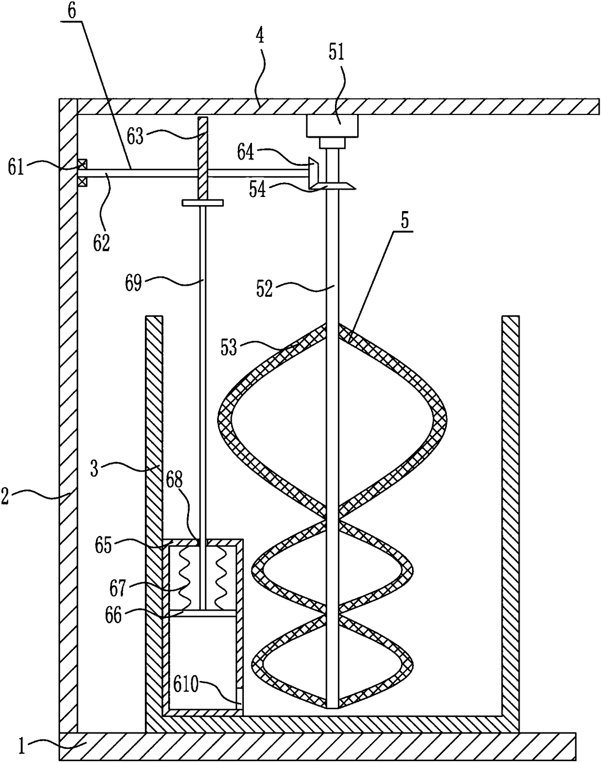
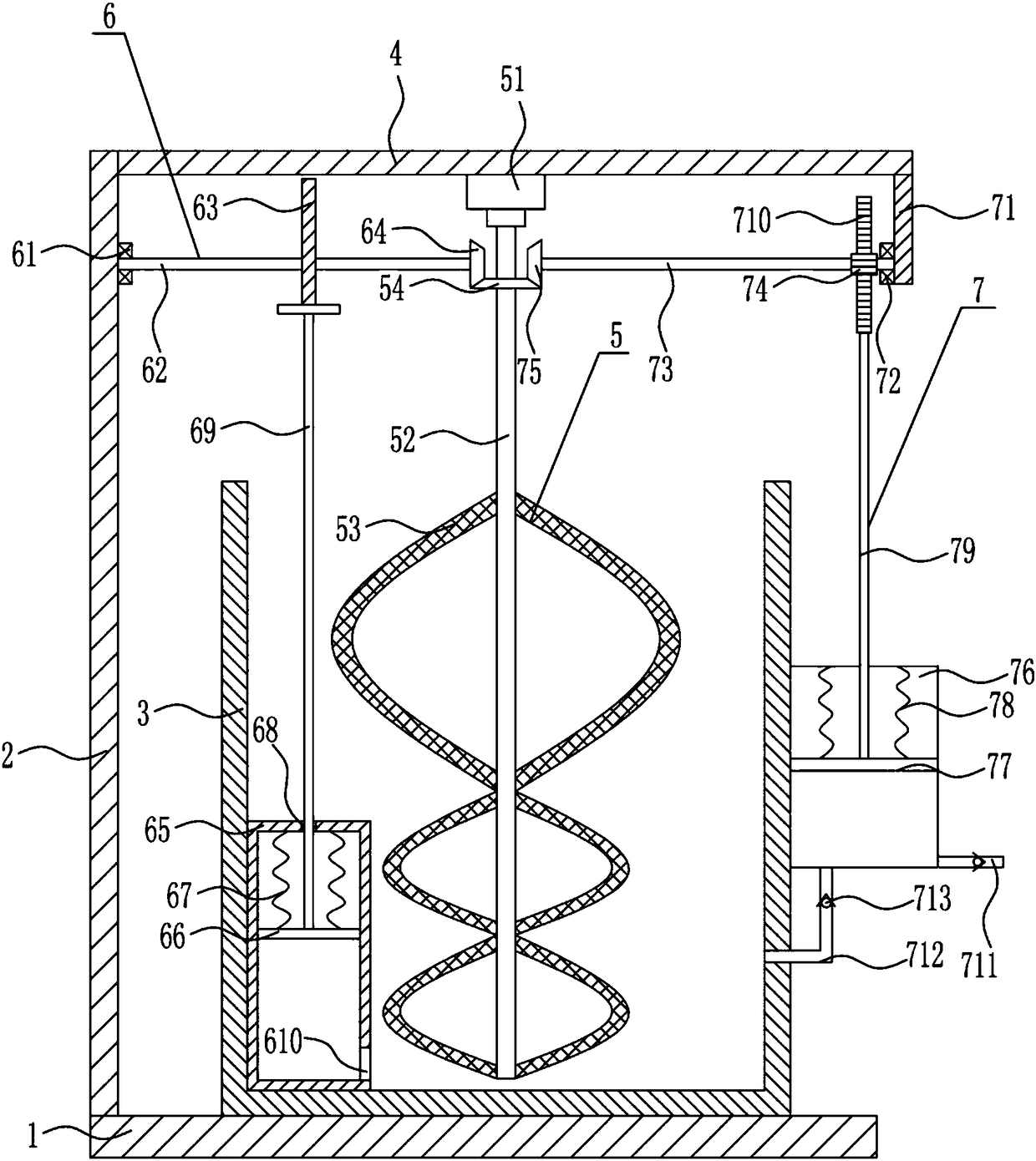
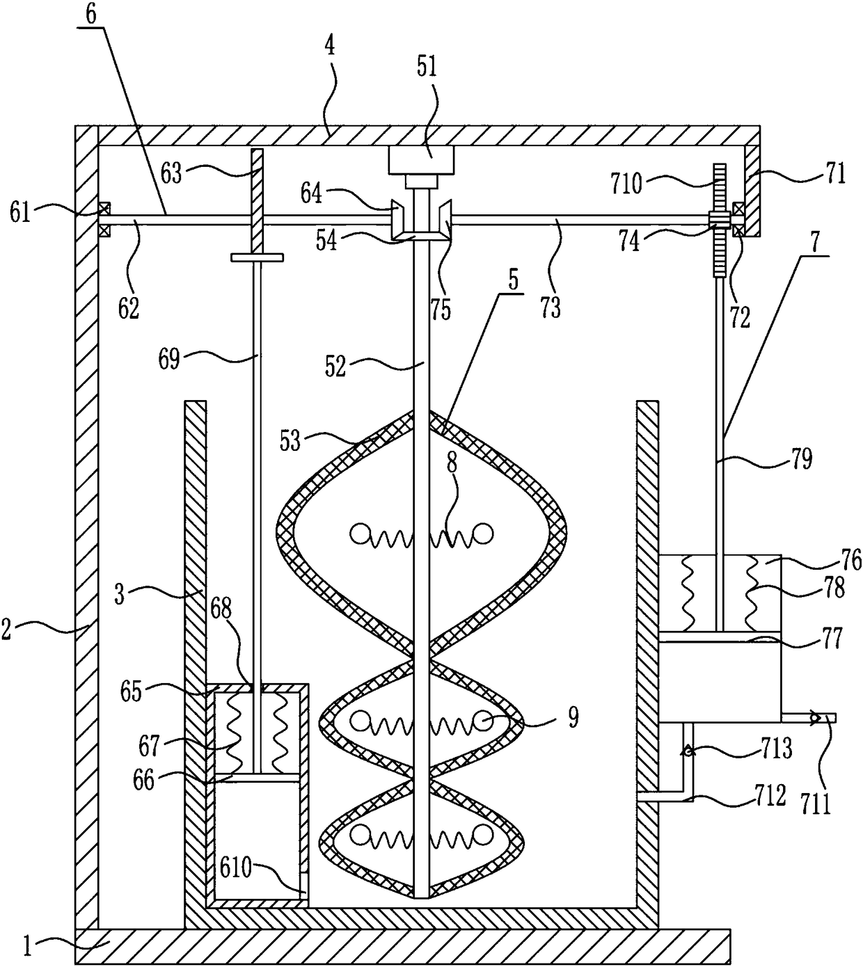
[0029] A dyeing agent preparation machine for textile dyeing, such as Figure 1-4 As shown, it includes a bottom plate 1, a left side plate 2, a box body 3, a top plate 4, a stirring mechanism 5 and a mixing mechanism 6. The left side plate 2 is provided on the left side of the top of the bottom plate 1, and the top plate is provided on the right side of the top of the left side plate 2. 4. There is a box 3 in the middle of the top of the bottom plate 1, a stirring mechanism 5 in the middle of the bottom of the top plate 4, and a mixing mechanism 6 on the left side of the inner bottom of the box 3.

Embodiment 2

[0031] A dyeing agent preparation machine for textile dyeing, such as Figure 1-4 As shown, it includes a bottom plate 1, a left side plate 2, a box body 3, a top plate 4, a stirring mechanism 5 and a mixing mechanism 6. The left side plate 2 is provided on the left side of the top of the bottom plate 1, and the top plate is provided on the right side of the top of the left side plate 2. 4. There is a box 3 in the middle of the top of the bottom plate 1, a stirring mechanism 5 in the middle of the bottom of the top plate 4, and a mixing mechanism 6 on the left side of the inner bottom of the box 3.

[0032] The stirring mechanism 5 includes a motor 51, a first rotating shaft 52, an arc-shaped net plate 53 and a first bevel gear 54, a motor 51 is installed in the middle of the bottom of the top plate 4, and the output shaft of the motor 51 is connected with the first rotating shaft 52, the first rotating shaft The lower part of the shaft 52 is symmetrically provided with an arc...

Embodiment 3

[0034] A dyeing agent preparation machine for textile dyeing, such as Figure 1-4 As shown, it includes a bottom plate 1, a left side plate 2, a box body 3, a top plate 4, a stirring mechanism 5 and a mixing mechanism 6. The left side plate 2 is provided on the left side of the top of the bottom plate 1, and the top plate is provided on the right side of the top of the left side plate 2. 4. There is a box 3 in the middle of the top of the bottom plate 1, a stirring mechanism 5 in the middle of the bottom of the top plate 4, and a mixing mechanism 6 on the left side of the inner bottom of the box 3.

[0035]The stirring mechanism 5 includes a motor 51, a first rotating shaft 52, an arc-shaped net plate 53 and a first bevel gear 54, a motor 51 is installed in the middle of the bottom of the top plate 4, and the output shaft of the motor 51 is connected with the first rotating shaft 52, the first rotating shaft The lower part of the shaft 52 is symmetrically provided with an arc-...


PUM


Abstract

The invention relates to a coloring agent preparation machine, in particular to a coloring agent preparation machine for textile dyeing. Against the technical problem to be solved, the invention provides a coloring agent preparation machine for textile dyeing, which is high in mixing efficiency, performs mixing evenly and is simple to operate. In order to solve the technical problem, the inventionprovides such a coloring agent preparation machine for textile dyeing which includes a base plate and the like. A left side plate is disposed on the left side of the top of the base plate, a top plate is disposed on the right side of the top of the left side plate, the middle of the top of the base plate is provided with a box body, a stirring mechanism is arranged at the middle of the bottom ofthe top plate, and a mixing mechanism is arranged on the left side of the bottom of the box body. According to the coloring agent preparation machine for textile dyeing, raw materials are stirred through the stirring mechanism, the raw materials are sucked into a first cylinder body through the mixing mechanism and then sprayed out, the mixing between the raw materials is accelerated, and the mutual contact is more sufficient.

Description

technical field [0001] The invention relates to a dyeing agent preparation machine, in particular to a dyeing agent preparation machine for textile dyeing. Background technique [0002] Textile is a product made of textile fibers through processing and weaving. It is divided into two categories: woven fabrics and knitted fabrics. China is one of the earliest countries in the world to produce textiles. The main production areas are Puyuan, Zhejiang Kongkong, Qinghe, Hebei and other places. . In a narrow sense, textiles refer to two series of woven fabrics and knitted fabrics. Broadly speaking, textiles are from spinning - weaving - finished products. [0003] The dyes can be divided into natural dyes and synthetic dyes according to the source. Different dyes are selected for different experiments, and the same dye can also be formulated with different formulas. [0004] During the preparation process of dyeing agent, various raw materials need to be mixed, and then the req...

Claims


Application Information

Patent Timeline
IPC IPC(8): B01F7/24B01F11/00B01F13/02B01F33/40
CPCB01F27/074B01F27/1141B01F27/118B01F27/19B01F27/92B01F31/443B01F31/449B01F31/441B01F33/402B01F33/4094B01F33/409B01F2101/30
Inventor 孙冲王弋毓叶芳亭
Owner 孙冲
Learn More