Novel unshaped refractory vibrator

A technology of refractory materials and vibrators, applied in furnaces, lining repairs, lighting and heating equipment, etc., can solve problems such as inability to guarantee construction quality, inconvenient installation and fixation, and inability of the vibration process to fully meet the technical requirements. The pounding effect is good, avoiding the effect of being stuck or missing vibration

Inactive Publication Date: 2018-06-22
浙江康斯迪冶金科技有限公司
View PDF1 Cites 0 Cited by
  • Summary
  • Abstract
  • Description
  • Claims
  • Application Information

AI Technical Summary

Problems solved by technology

[0002] The construction of unshaped refractory castables has been more and more used in industrial furnaces. The construction of unshaped refractory castables mainly depends on the mold and vibration, especially the refractory casting in structural parts with thinner thickness and larger molds. How to ensure the construction quality requires higher technical requirements. Taking the construction of refractory castables for vaporization furnace as an example, the mold is made of steel, the thickness of the steel plate is 5mm, and the height of the support is 4m. The difficulty of this structure is that the thickness of the castable is relatively high. Thin, denser anchor nails are arranged in the castable, if a vibrating rod is used, it may cause the vibrating rod to be stuck or leak vibration, and the vibrating process cannot fully meet the technical requirements, and the quality of the construction cannot be guaranteed
[0003] The patent application number 201220386644.5 proposes a new type of unshaped refractory vibrator. It is very inconvenient to install and fix it by means of screws, and its vibration amplitude cannot be adjusted. Therefore, we propose a new type of unshaped refractory vibrator. vibrator

Method used


Image

  • Novel unshaped refractory vibrator
  • Novel unshaped refractory vibrator
  • Novel unshaped refractory vibrator

Examples


Embodiment Construction

[0020] The following will clearly and completely describe the technical solutions in the embodiments of the present invention with reference to the accompanying drawings in the embodiments of the present invention. Obviously, the described embodiments are only some, not all, embodiments of the present invention.

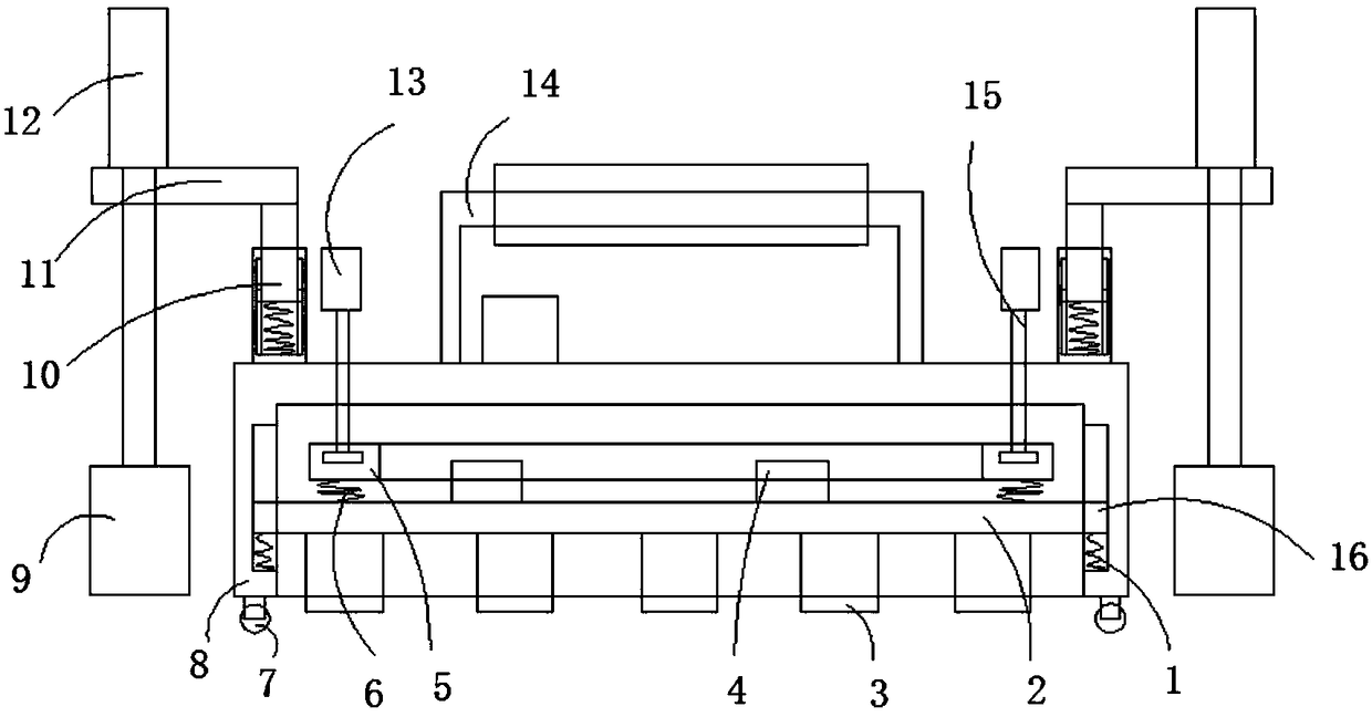
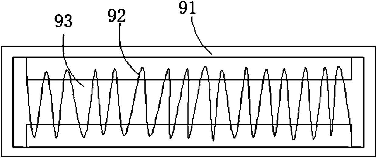
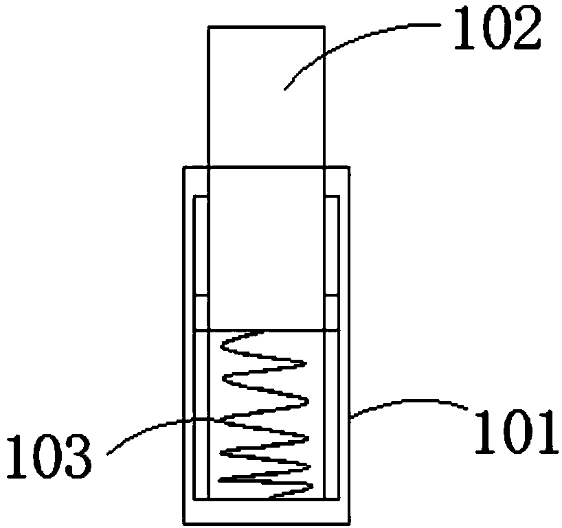
[0021] refer to Figure 1-3 , a new type of unshaped refractory vibrator, including an installation box 8 with an open bottom end, four vertically arranged threaded rods 15 are rotatably connected to the top side wall of the installation box 8, and the bottom end of the threaded rod 15 is rotatably connected to a horizontally arranged The adjustment ring 5 is located inside the installation box 8, and the bottom end of the adjustment ring 5 is connected with a plurality of second springs 6, and the bottom end of the second spring 6 is connected with a vibrating plate body 2 arranged horizontally, and the vibrating plate body A plurality of vibrating motors 4 are inst...


PUM


Abstract

The invention discloses a novel unshaped refractory vibrator comprising an installation box with an opening at the bottom end; the side wall of the top end of the installation box is rotatably connected with four threaded rods which are vertically arranged; bottom ends of the threaded rods are rotatably connected with adjusting rings which are horizontally arranged; the adjusting rings are locatedin the installation box; the bottom ends of the adjusting rings are connected with multiple second springs; the bottom ends of the second springs are connected with a vibration plate body which is arranged horizontally; the side wall of the top end of the vibration plate body is provided with multiple vibration motors; the vibration plate body is connected inside the installation box in a slidingmode; the bottom end of the vibration plate body is provided with multiple vibration blocks which are distributed in an array mode; and two sides of the top end of the installation box are all provided with fixing devices. The novel unshaped refractory vibrator can be easily installed and fixed on a metal mold, the vibration amplitude can be adjusted, and vibration is carried out at the outer side of the mold, so as to prevent a vibrator rod from being stuck or shock leaking when internal vibration occurs, and the vibrating effect is good.

Description

technical field [0001] The invention relates to the technical field of vibrators, in particular to a novel unshaped refractory vibrator. Background technique [0002] The construction of unshaped refractory castables has been more and more used in industrial furnaces. The construction of unshaped refractory castables mainly depends on the mold and vibration, especially the refractory casting in structural parts with thinner thickness and larger molds. How to ensure the construction quality requires higher technical requirements. Taking the construction of refractory castables for vaporization furnace as an example, the mold is made of steel, the thickness of the steel plate is 5mm, and the height of the support is 4m. The difficulty of this structure is that the thickness of the castable is relatively high. Thin, denser anchor nails are arranged in the castable. If a vibrating rod is used, it may cause the vibrating rod to be stuck or leak vibration. The vibrating process ca...

Claims


Application Information

Patent Timeline
Patent Type & Authority Applications(China)
IPC IPC(8): F27D1/16
CPCF27D1/1626
Inventor 杨振新
Owner 浙江康斯迪冶金科技有限公司
Why Eureka
Try Eureka