
Pressure control valve group, automatic debugging system, pumping device and automatic debugging method for pumping device debugging

A technology for pressure control and pumping equipment, applied in pump control, mechanical equipment, machines/engines, etc., can solve problems such as poor linearity of water valve adjustment, sudden change in load pressure, and low overall efficiency, achieving high precision and low batch cost Low, high safety effect

Active Publication Date: 2018-06-22
CHANGDE KEJIAN MACHINERY MFG CO LTD
View PDF8 Cites 1 Cited by
  • Summary
  • Abstract
  • Description
  • Claims
  • Application Information

AI Technical Summary

Problems solved by technology

Among them, due to the poor linearity of the adjustment of the water valve of the mechanical ball valve structure, it is easy to cause a sudden change in the load pressure, and it is easy to cause the water valve to be washed out by high-pressure water, and the safety factor is low; Low

Method used


Image

  • Pressure control valve group, automatic debugging system, pumping device and automatic debugging method for pumping device debugging
  • Pressure control valve group, automatic debugging system, pumping device and automatic debugging method for pumping device debugging
  • Pressure control valve group, automatic debugging system, pumping device and automatic debugging method for pumping device debugging

Examples


Embodiment Construction

[0037] Specific embodiments of the present invention will be described in detail below in conjunction with the accompanying drawings. It should be understood that the specific embodiments described here are only used to illustrate and explain the present invention, and are not intended to limit the present invention.

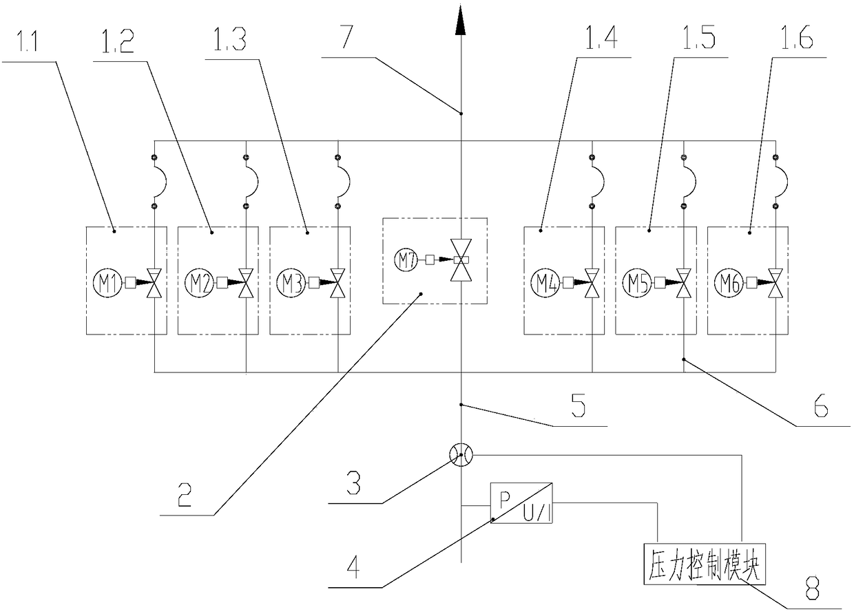
[0038] refer to figure 1 , in the preferred mode of the present invention, the present invention provides a pressure control valve group for pumping equipment debugging, the device includes a plurality of flow regulating valves 1.1- 1.6 and relief valve 2, multiple flow regulating valves 1.1-1.6 and relief valve 2 are connected in parallel, and multiple flow regulating valves 1.1-1.6 and relief valve 2 are driven by stepper motors M1-M7; pressure control valve group It also includes a pressure control module 8 for controlling the actions of the stepping motors M1-M7. Preferably, the pressure control valve group further includes a flow detection element 3 and a...


PUM


Abstract

The invention provides a pressure control valve group for pumping device debugging; the pressure control valve group comprises multiple flow control valves and an overflow valve which are connected between a water inlet pipe and a water outlet pipe; the multiple flow control valves and the overflow valve are connected in parallel, and the multiple flow control valves and the overflow valve are alldriven by a stepping motor; and the pressure control valve group also comprises a pressure control module used for controlling movement of the stepping motor. Through-flow sectional areas of the flowcontrol valves and the overflow valve are controlled by arranging the pressure control module to control the movement of the stepping motor, the required simulated load pressure can be adjusted automatically, so that the pumping debugging of the pumping device is efficient, safe and accurate.

Description

technical field [0001] The invention relates to a hydraulic debugging technology, in particular to a pressure control valve group for pumping equipment, an automatic debugging system, pumping equipment and an automatic debugging method. Background technique [0002] At present, the pumping hydraulic system adopted by most manufacturers of concrete pumping equipment (such as concrete pump trucks, vehicle pumps, trailer pumps, cement mortar pumps, etc.) is a water valve with a complete mechanical ball valve structure. In the process of pump water debugging, the opening of the ball valve is manually adjusted to simulate the concrete medium as the output load of the pumping unit, and at the same time adjust the mechanical constant power device of the main pump or the displacement value of the main pump to achieve the debugging of the constant power of the main pump. Purpose. Among them, due to the poor linearity of the adjustment of the water valve of the mechanical ball valve ...

Claims


Application Information

Patent Timeline
Patent Type & Authority Applications(China)
IPC IPC(8): F04B49/00
Inventor 陈远龙陈孝金胡忠保张进王先舫
Owner CHANGDE KEJIAN MACHINERY MFG CO LTD
Learn More