Shifting unit for gantry type CNC machining center

A processing center and mobile device technology, applied in metal processing equipment, metal processing machinery parts, manufacturing tools, etc., can solve the problems of no moving function, no shock absorption and buffering effect, etc.

Inactive Publication Date: 2018-06-22
郭文英
View PDF8 Cites 6 Cited by
  • Summary
  • Abstract
  • Description
  • Claims
  • Application Information

AI Technical Summary

Problems solved by technology

However, the existing gantry-type CNC machining center devices do not have a moving function

Method used


Image

  • Shifting unit for gantry type CNC machining center
  • Shifting unit for gantry type CNC machining center
  • Shifting unit for gantry type CNC machining center

Examples


Embodiment

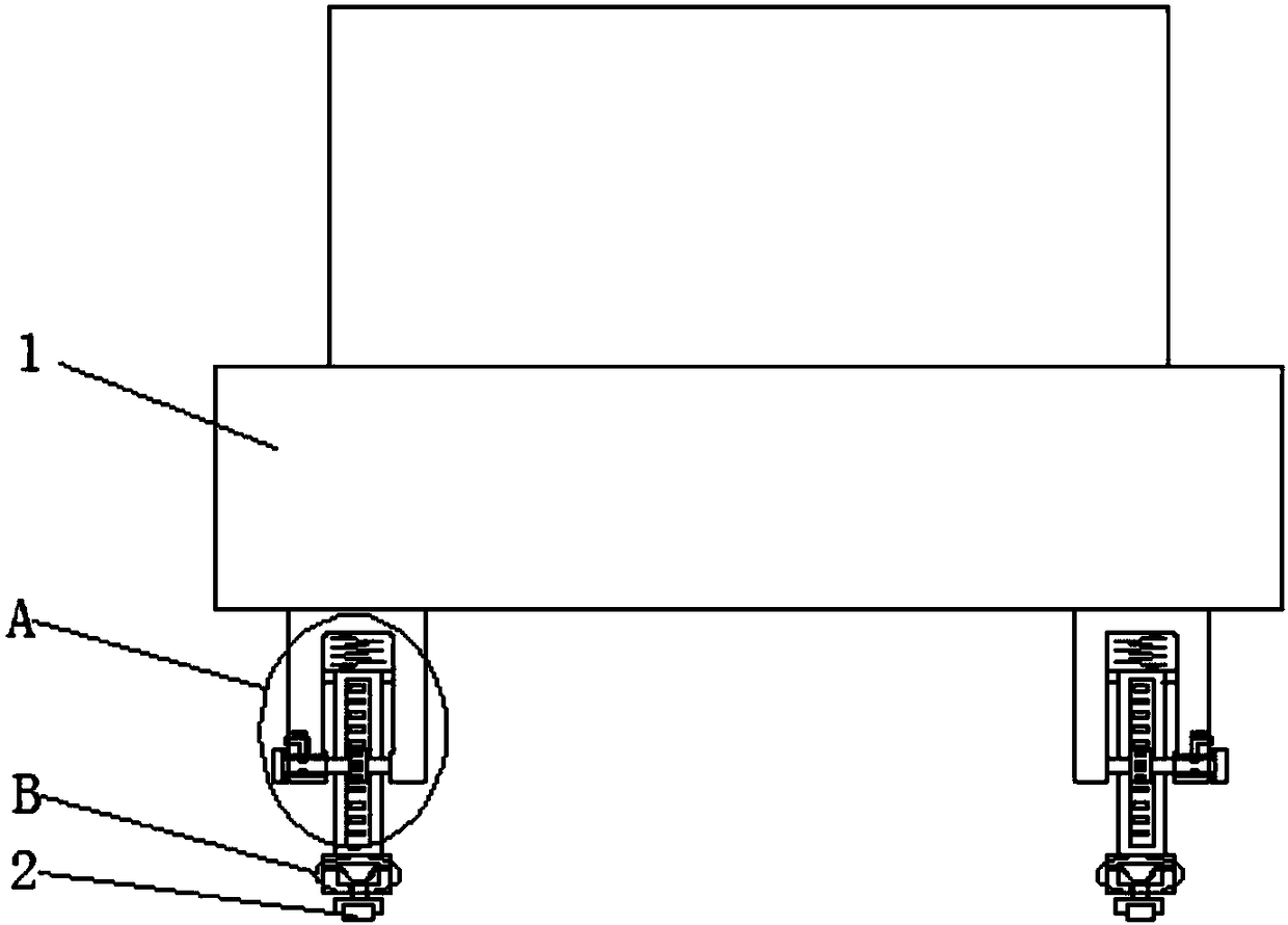
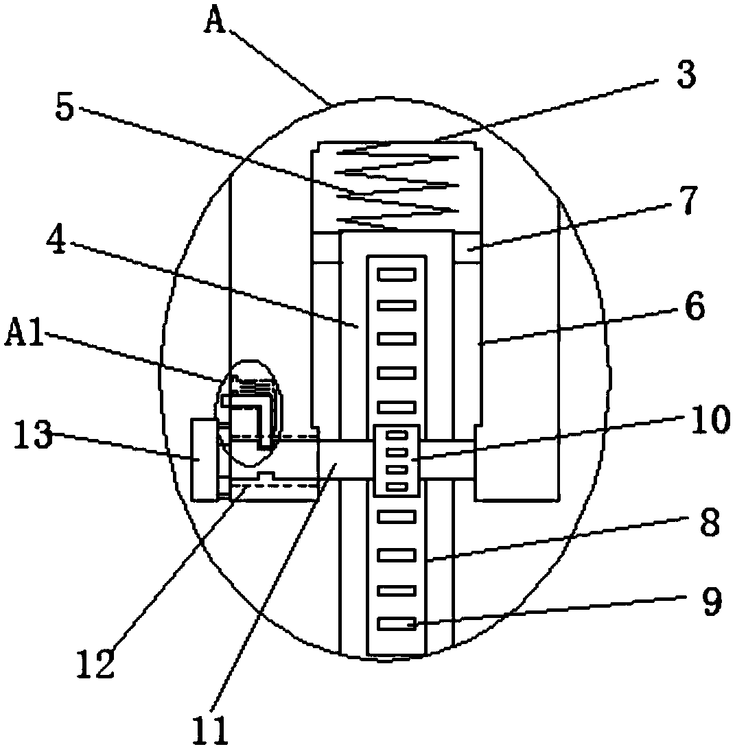
[0025] refer to Figure 1-6, a mobile device for a gantry type CNC machining center, comprising a base 1 and a CNC machining device fixedly installed on the top side of the base 1, fixed rods are fixedly installed at the four corners of the bottom side of the base 1, and a sliding door is provided at the bottom end of the fixed rod Groove 3, a sliding rod 4 is slidably installed in the sliding groove 3, the bottom end of the sliding rod 4 extends to the outside of the sliding groove 3, and a universal wheel 2 is installed, and a placement groove 8 is provided on one side of the sliding rod 4, A rack 9 is fixedly installed in the placement groove 8 along the vertical direction, and a gear 10 located in the sliding groove 3 is meshed on the rack 9. A rotating rod 11 is fixedly installed on the end of the gear 10 away from the center position of the bottom side of the base 1, and slides There is a turning hole 12 on the inner wall of the groove 3 away from the center position of ...


PUM


Abstract

The invention discloses a shifting unit for a gantry type CNC machining center. The shifting unit comprises a base and a CNC machining device, wherein the CNC machining device is fixedly arranged on the top side of the base; and fixing rods are fixedly arranged at the four corners of the bottom side of the base respectively, sliding grooves are formed in the bottom ends of the fixing rods, slidingrods are slidably arranged in the sliding grooves, the bottom ends of the sliding rods extend out of the sliding grooves and are provided with universal wheels, containing grooves are formed in one sides of the sliding rods, racks are fixedly arranged in the containing grooves in the vertical direction, gears positioned in the sliding grooves mesh with the racks, rotating rods are fixedly arranged at the ends, far away from the center of the bottom side of the base, of the gears, and rotating holes are formed in the inner walls of the sides, far away from the center of the bottom side of thebase, of the sliding grooves. According to the shifting unit, the height of the base can be stabilized and adjusted conveniently, and meanwhile, when the base moves through the universal wheels and machining is carried out, a certain buffering effect can be achieved conveniently.

Description

technical field [0001] The invention relates to the technical field of CNC machining, in particular to a moving device for a gantry type CNC machining center. Background technique [0002] Traditional machining centers are generally used for processing larger parts, so their volume is also relatively large. And most of them adopt the cantilever type, so when performing high-speed machining, the vibration is relatively large, which affects the machining accuracy. With the gradual rise of the auto parts and instrument industry, it has gradually become an indispensable requirement to use miniaturized or even desktop equipment to process parts. The existing engraving and milling machines and engraving machines can meet the above requirements to a certain extent . Although traditional engraving and milling machines or engraving machines can process small parts, they can only process soft metals and cannot perform heavy cutting. Therefore need a kind of novel desk-like, small p...

Claims


Application Information

Patent Timeline
IPC IPC(8): B23Q1/72B23Q11/00
CPCB23Q1/72B23Q11/0032
Inventor 郭文英
Owner 郭文英
Why Eureka
Try Eureka