


Quick Research
Generate reliable direction feasibility study reports for your R&D in just a few steps.

Technical Q&A
Discover and master advanced knowledge NOW. Basics, ideas, possibilities, all at once.

Find Solutions
As an expert in R&D theories, this can generate solutions to your technical problems instantly.

Evaluate Feasibility
Analyze your overall solution with one click, know your potential R&D risks in advance.

Monitor Landscape
Get weekly tech updates, stay abreast of the latest tech innovations and key insights.
Surgical robot terminal
A technology of surgical robots and surgical instruments, applied in the field of medical equipment, to achieve the effect of simplifying the overall structure and quality
- Summary
- Abstract
- Description
- Claims
- Application Information
AI Technical Summary
Problems solved by technology
Method used
Image


Examples
Embodiment 1
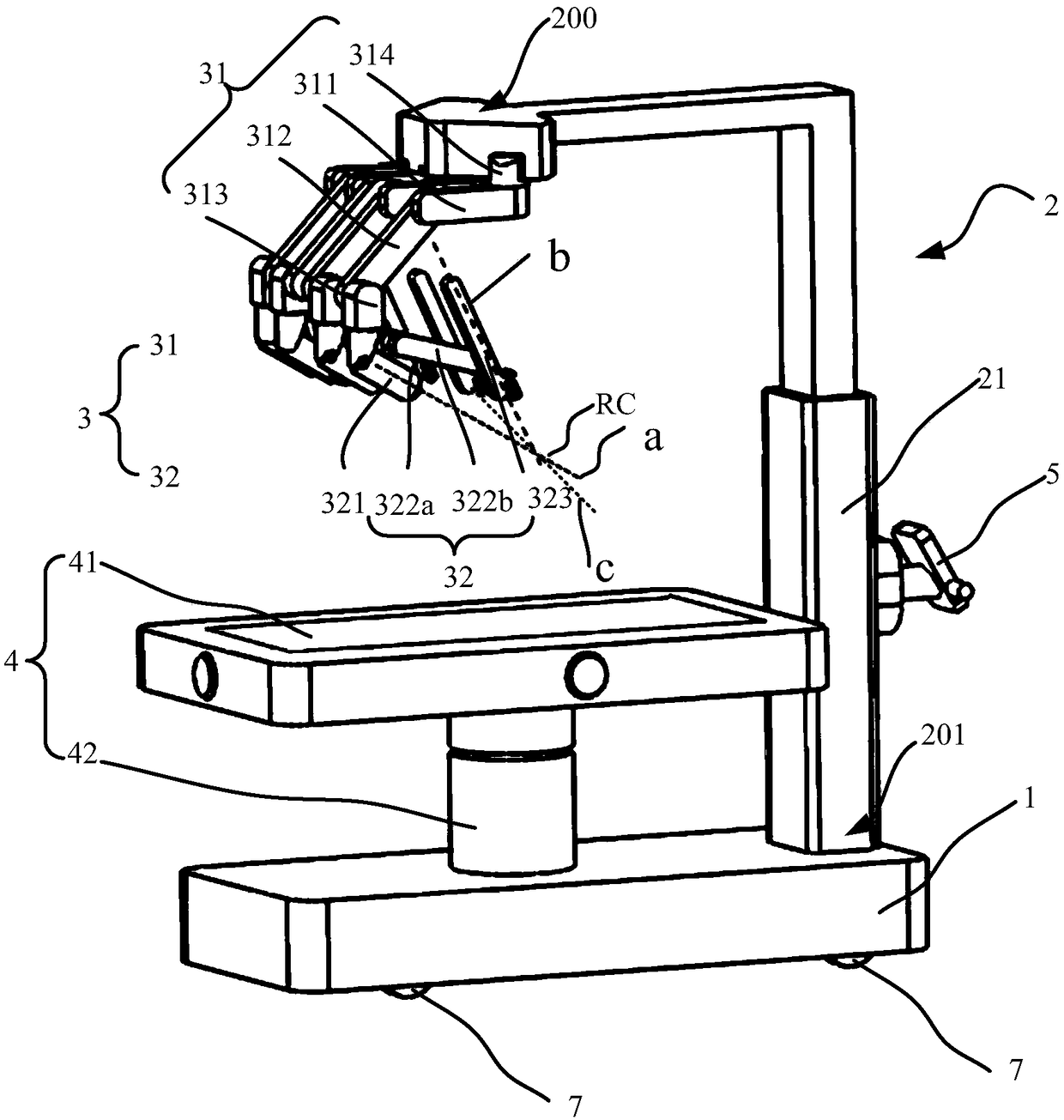
[0082] Please refer to figure 1 , the surgical robot terminal of the present invention mainly includes: a base 1 , a column 2 , at least one mechanical arm 3 and a hospital bed 4 . Such as figure 1 As shown, the surgical robot terminal includes: a base 1, a column 2, four mechanical arms 3 and a hospital bed 4; wherein, each mechanical arm 3 includes an adjustment arm 31 and a tool arm 32; the tool arm 32 and A surgical instrument is connected, and the tool arm 32 is used to drive the surgical instrument to move around a fixed point; the distal end of the adjustment arm 31 is connected to the tool arm 32, preferably, the distal end of the adjustment arm 31 end and the tool arm 32 are rotationally connected; the adjusting arm 31 is used to adjust the spatial position of the fixed point; the sick bed 4 is connected to the base 1, and the sick bed 4 includes a first rotary joint, a second Two rotary joints and a third rotary joint, and the rotary axis of the first rotary joint,...
Embodiment 2
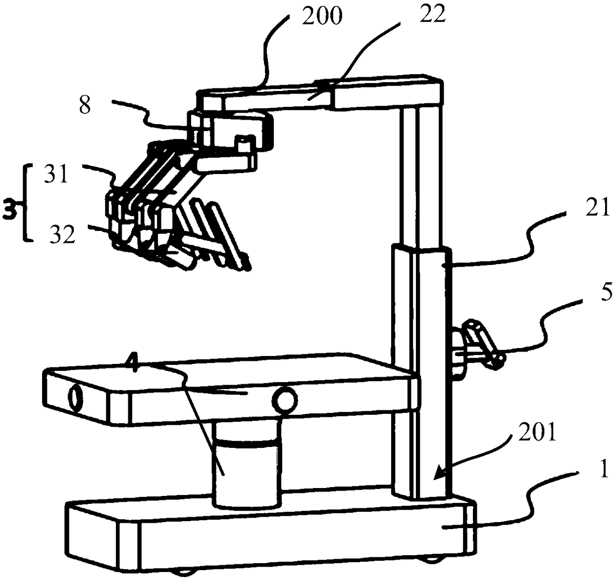
[0106] Please refer to figure 1 and Figure 5 , Figure 5 It is the front view of the surgical robot terminal in this embodiment. Compared Figure 5 and figure 1 It can be seen from the front view of the surgical robot terminal shown that the two figures show two configurations of the surgical robot terminal, and the main difference is reflected in the structure of the column 2 . Specifically, although figure 1 The example shown and Figure 5 In the shown embodiment, the relative positions of the column 2 and the hospital bed remain unchanged, but the specific implementation methods are different. figure 1 Among them, the base end 201 of the column 2 (that is, the end opposite to the suspension end 200 in the column) is fixedly connected to the base 1; Figure 5 Among them, the base end 201 of the upright column 2 (that is, the end of the upright column except the suspension end 200 ) is fixedly connected with the hospital bed 4 . In a specific embodiment, the bed body...
Embodiment 3
[0110] Please refer to Figure 7 , which is the front view of the surgical robot terminal in this embodiment. The configuration difference between embodiment three and embodiment one and embodiment two is: in embodiment one and embodiment two, the relative position of column 2 and hospital bed 4 remains unchanged (that is, the relative position of column 2 and hospital bed 4 cannot be adjusted); However, in the third embodiment, the relative position of the upright column 2 to the hospital bed 4 can be adjusted (that is, the upright column 2 can move closer to or farther away from the hospital bed 4 ).
[0111] Such as Figure 7 As shown, the surgical robot terminal includes at least one mechanical arm 3, a hospital bed 4, a base 1 and a column 2. The mechanical arm 3 includes an adjustment arm 31 and a tool arm 32; the tool arm 32 is connected to a surgical instrument , the tool arm 32 is used to drive the surgical instrument to move around a fixed point; the distal end of ...
PUM
 Abstract
Description
Claims
Application Information
 - R&D Engineer
- R&D Manager
- IP Professional
- Industry Leading Data Capabilities
- Powerful AI technology
- Patent DNA Extraction
Browse by: Latest US Patents, China's latest patents, Technical Efficacy Thesaurus, Application Domain, Technology Topic, Popular Technical Reports.
© 2024 PatSnap. All rights reserved.Legal|Privacy policy|Modern Slavery Act Transparency Statement|Sitemap|About US| Contact US: help@patsnap.com