


Quick Research
Generate reliable direction feasibility study reports for your R&D in just a few steps.

Technical Q&A
Discover and master advanced knowledge NOW. Basics, ideas, possibilities, all at once.

Find Solutions
As an expert in R&D theories, this can generate solutions to your technical problems instantly.

Evaluate Feasibility
Analyze your overall solution with one click, know your potential R&D risks in advance.

Monitor Landscape
Get weekly tech updates, stay abreast of the latest tech innovations and key insights.
Multifunctional vegetable aeroponic cultivation equipment
An aerosol cultivation, multi-functional technology, applied in the field of plant cultivation equipment, can solve the problems of uneven lighting of vegetables, inconvenient maintenance and the like
- Summary
- Abstract
- Description
- Claims
- Application Information
AI Technical Summary
Problems solved by technology
Method used
Image

Examples
Embodiment 1
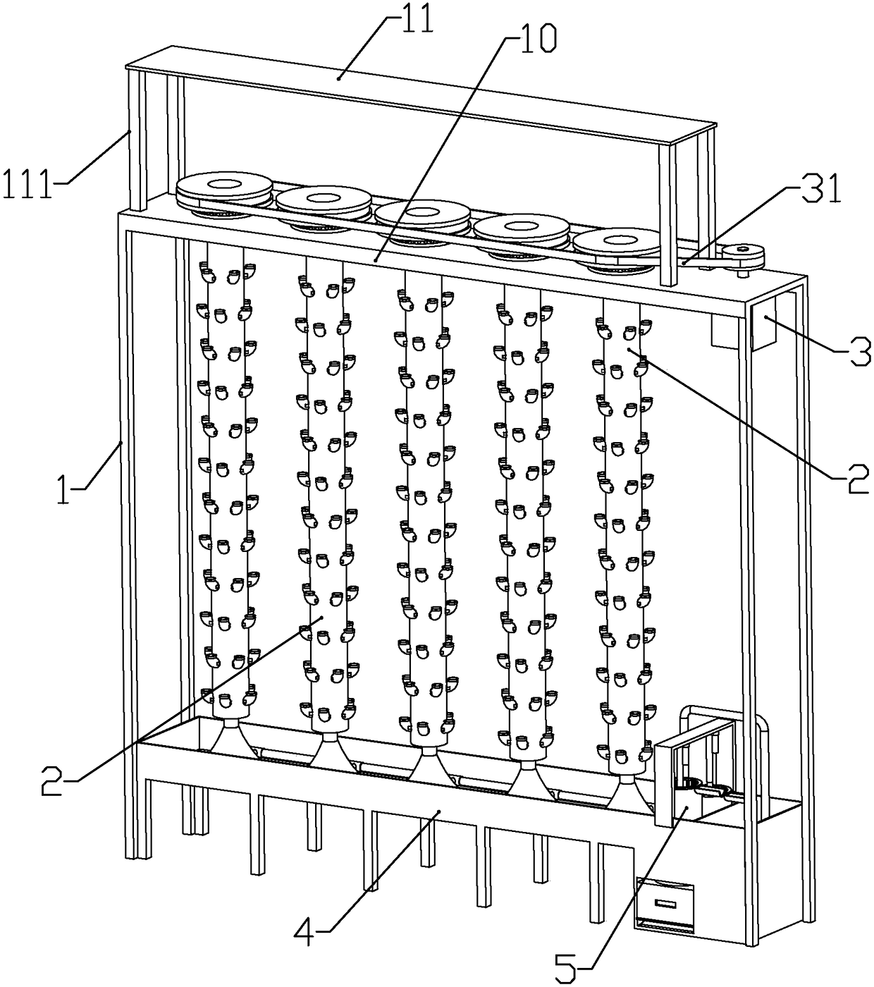
[0094] according to Figure 1 to Figure 15 As shown, the present embodiment is a multifunctional vegetable aerosol cultivation equipment, including a support 1, a plurality of longitudinally arranged planting components 2 rotatably mounted on the lower end of the support, and a water tank 4 arranged below each planting component.
[0095] A horizontal mounting plate 10 is fixedly connected to the upper end of the bracket, a solar panel mounting frame 111 is fixedly connected to the top of the mounting plate, and a solar battery panel 11 is mounted on the upper end of the solar panel mounting frame.
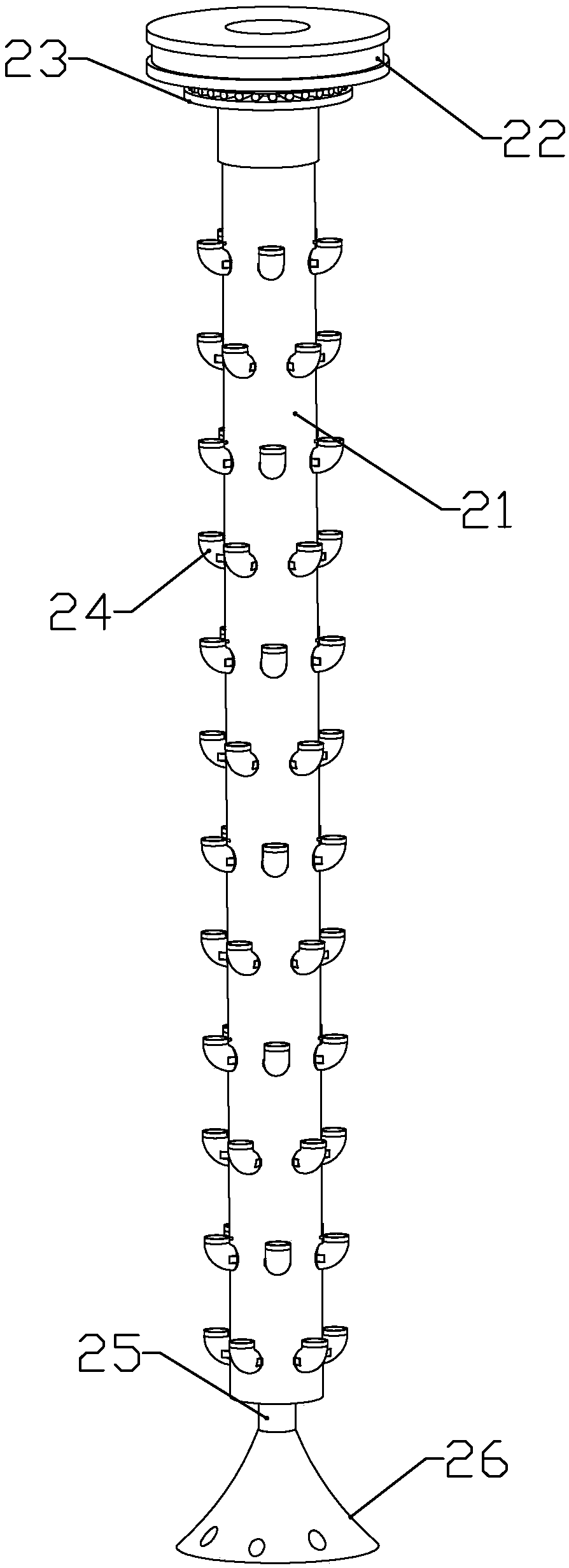
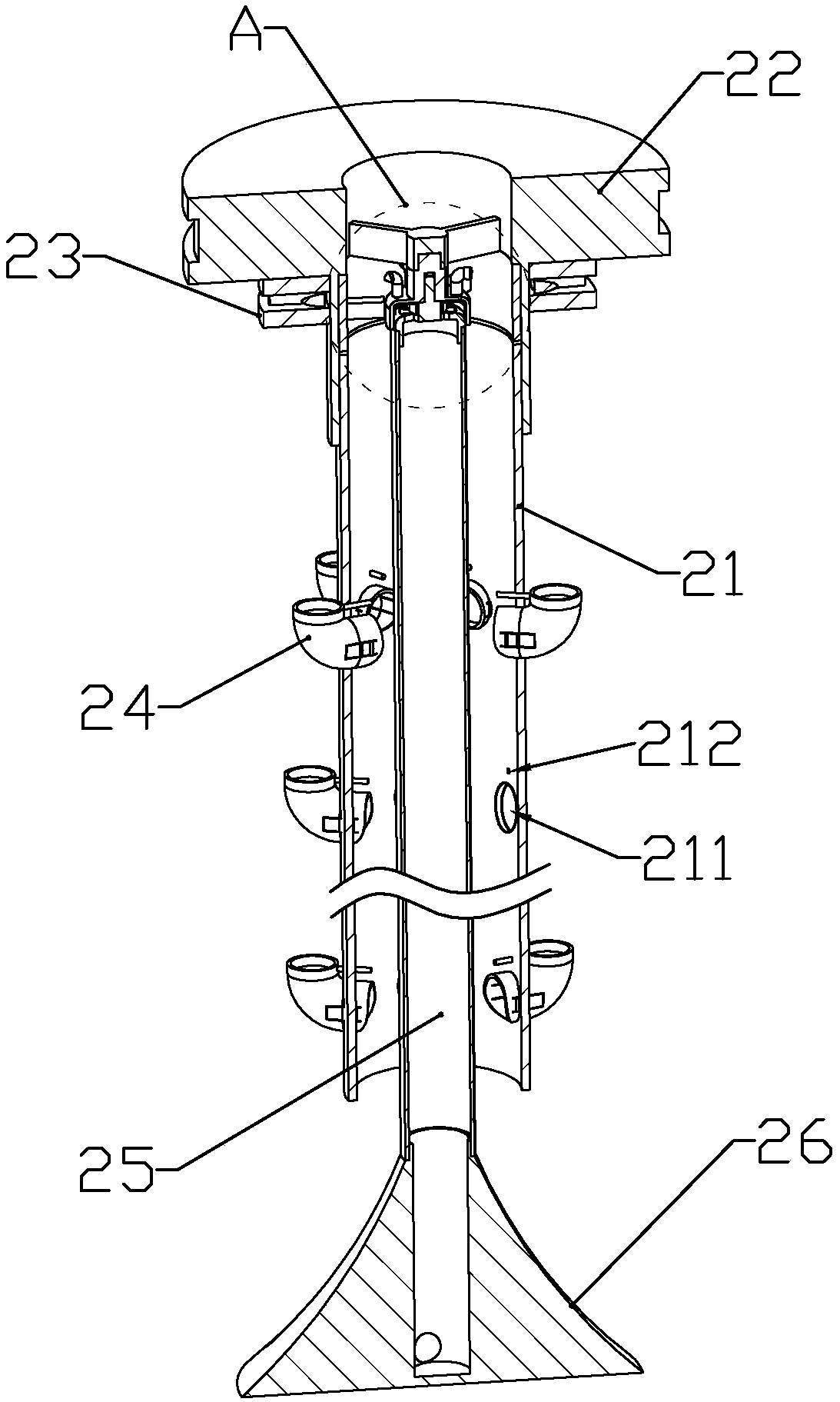
[0096] The planting assembly includes a pulley 22 arranged horizontally above the mounting plate, a bearing 23 connected between the mounting plate and the pulley (the bearing is a radial-axial composite bearing), and a planting plate coaxially connected to the lower end of the pulley. Pipe 21, a plurality of planting elbows 24 installed on the outer wall of the planting pipe and ...
Embodiment 2
[0109]This embodiment also makes the following improvements on the basis of Embodiment 1: the lower end of the water receiving tank body 41 is formed with two longitudinally arranged cylindrical filter installation ports 44 near the clean water tank body, and the water tank is located on two A waste water tank installation port 43 arranged horizontally is formed below the first filter installation port, and a filter assembly 5 is respectively slidably installed in the two filter installation ports, and a waste water box 52 is installed in the waste water tank installation port.
[0110] Two waste water tanks 521 are formed on the waste water box 52; more than two upper bumps 421 are formed on the inner bottom of the waste water tank installation opening, and a lower slope 4211 is formed on the side of the upper protrusion close to the opening of the waste water tank installation opening; A clamping push plate 54 is slidingly installed at the bottom of the installation opening o...
Embodiment 3
[0124] This embodiment makes the following improvements on the basis of Embodiment 1 or 2: the part of the bracket located below the mounting plate is covered with a cover made of a transparent film or acrylic plate, and the upper part of the cover is connected to an input channel connected to the room. trachea. In this way, the filtered air can be introduced into the room, that is, the present invention can be used as an air purifier.
PUM
 Abstract
Description
Claims
Application Information
 - R&D Engineer
- R&D Manager
- IP Professional
- Industry Leading Data Capabilities
- Powerful AI technology
- Patent DNA Extraction
Browse by: Latest US Patents, China's latest patents, Technical Efficacy Thesaurus, Application Domain, Technology Topic, Popular Technical Reports.
© 2024 PatSnap. All rights reserved.Legal|Privacy policy|Modern Slavery Act Transparency Statement|Sitemap|About US| Contact US: help@patsnap.com