
Parallax correction method, device and terminal

A parallax correction and parallax technology, applied in image data processing, instruments, calculations, etc., can solve problems such as difficult to balance filtering effect and poor filtering effect of the entire parallax image.

Active Publication Date: 2018-06-19
HISENSE
View PDF7 Cites 3 Cited by
  • Summary
  • Abstract
  • Description
  • Claims
  • Application Information

AI Technical Summary

Problems solved by technology

[0005] The present invention provides a parallax correction method, device, and terminal to solve the problem of using a fixed window to filter parallax images in the prior art, and it is difficult to balance the filtering effect of parallax points on objects located at different distances from the parallax image, thereby A technical problem that makes the filtering effect of the entire parallax image poor

Method used


Image

  • Parallax correction method, device and terminal
  • Parallax correction method, device and terminal
  • Parallax correction method, device and terminal

Examples


Embodiment Construction

[0061] In order to make the purpose, technical solutions and advantages of the present invention clearer, the present invention will be further described in detail below in conjunction with the accompanying drawings. Obviously, the described embodiments are only some of the embodiments of the present invention, not all of them. Based on the embodiments of the present invention, all other embodiments obtained by persons of ordinary skill in the art without making creative efforts belong to the protection scope of the present invention.

[0062] The embodiments of the present invention will be further described in detail below in conjunction with the accompanying drawings.

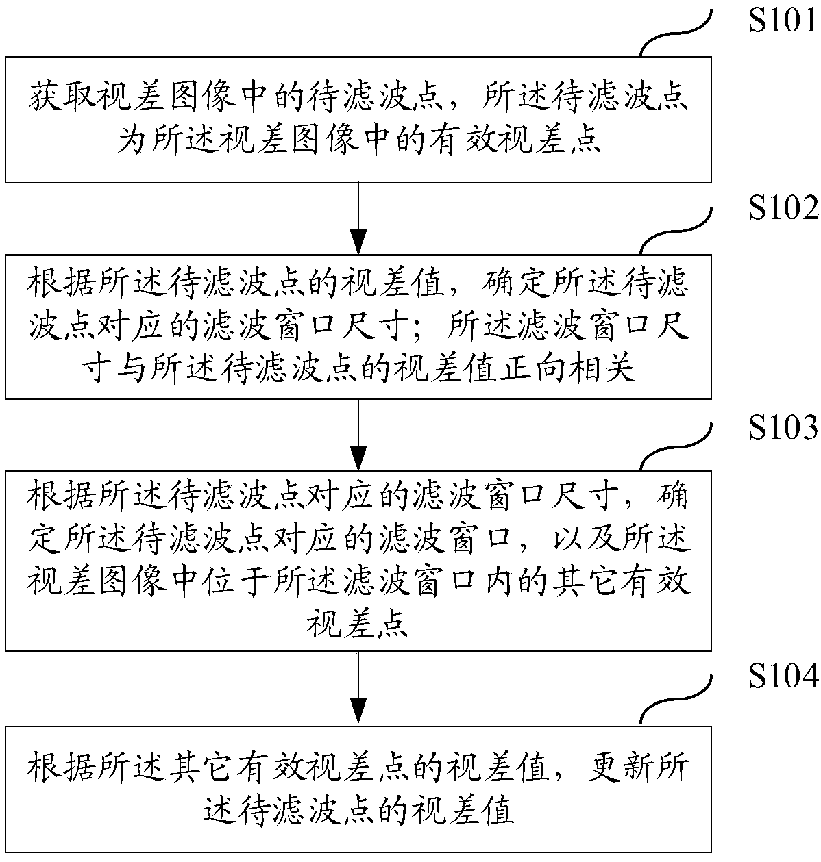
[0063] figure 1 A schematic flowchart corresponding to a parallax correction method provided in an embodiment of the present invention is shown, as shown in figure 1 As shown, the method includes:

[0064] Step S101: Obtain the point to be filtered in the parallax image, the point to be filtered is an effe...


PUM


Abstract

The embodiment of the invention discloses a parallax correction method, device and terminal. The method comprises: acquiring a point to be filtered in a parallax image, determining a filtering windowsize according to the parallax value of the point to be filtered, wherein the size is positively correlated with the parallax value; determining the filtering window of the point to be filtered and updating the parallax value of the point to be filtered according to the parallax value of the valid parallax point in the filtering window. Since the filtering window size can be set to be positively correlated with the parallax value of the point to be filtered, in view that the parallax value is inversely proportional to the distance and the different filtering effects are required according to different distances, and the closer the distance is, the larger the filtering window of the point to be filtered is, and the farther the distance is, the smaller the filtering window of the point to befiltered is. When the parallax value of the point to be filtered is corrected, the filtering effect of the parallax points at different distances can be well balanced according to the parallax valuesof other valid parallax points in the filtering window, thereby effectively smoothing the parallax image and reducing the late detection and recognition difficulty.

Description

technical field [0001] The present invention relates to the technical field of driving assistance, in particular to a parallax correction method, device and terminal. Background technique [0002] Binocular stereo vision is to simulate the mechanism of human binocular recognition of three-dimensional information of the scene, obtain two-dimensional images of the scene from two angles, and then obtain the parallax image by establishing the matching relationship between the images, and then obtain the original image according to the principle of triangulation Depth information, including camera calibration, image correction, binocular image matching and other main processes, among which the establishment of the corresponding relationship between the pixels of the two images is the process of stereo matching, which is the core of binocular stereo vision. [0003] In order to facilitate subsequent accurate object detection or distance measurement using the parallax image, it is ...

Claims


Application Information

Patent Timeline
IPC IPC(8): G06T5/00
CPCG06T5/70
Inventor 冯谨强
Owner HISENSE
Learn More