
Dual reactive gas driven high-speed launching system

A gas-driven, launch system technology, applied in the direction of compressed air guns, weapons without explosives, offensive equipment, etc., can solve the problems of high price, low gas density, and rapid decrease in efficiency, and achieve simple structure, increased energy density, and increased initial The effect of pressure

Inactive Publication Date: 2019-09-10
INST OF FLUID PHYSICS CHINA ACAD OF ENG PHYSICS
View PDF9 Cites 0 Cited by
  • Summary
  • Abstract
  • Description
  • Claims
  • Application Information

AI Technical Summary

Problems solved by technology

[0004] However, the density of the gas is small, and the energy released by the unit volume of the gas reaction (that is, the energy density) is low. To obtain a higher energy density, the method of reducing the initial temperature or increasing the initial pressure can be adopted. Reducing the initial temperature involves a complex cryogenic system. , the price is expensive, and for the initial 300K gas, even if the temperature is reduced to 77K in the liquid nitrogen temperature zone, under the ideal gas assumption, the gas density (unliquefied) will only increase by a little more than 3 times. Initial pressure is a more efficient way to increase energy density
If an ordinary booster pump is used to increase the gas pressure, there are problems such as limited final pressure, bulky equipment, and rapid decrease in efficiency as the gas pressure in the container increases.

Method used


Image

  • Dual reactive gas driven high-speed launching system
  • Dual reactive gas driven high-speed launching system
  • Dual reactive gas driven high-speed launching system

Examples


Embodiment Construction

[0020] The present invention will be further described in detail below in conjunction with the accompanying drawings and embodiments, but it does not imply any limitation to the content of the present invention.

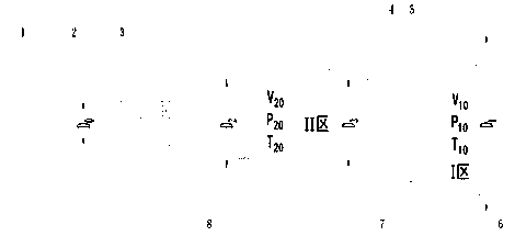
[0021] Such as figure 1 , a dual-reaction gas-driven high-speed launch system, comprising a launch tube 1 with projectiles 2, a reaction chamber, a diaphragm 3 located between the reaction chamber and the launch tube 1, characterized in that a piston 7 is housed in the reaction chamber, The piston 7 isolates the reaction chamber into two regions, the reaction chamber I zone 5 and the reaction chamber II zone 4, wherein the diaphragm 3 is located at the end of the reaction chamber II zone 4, and the reaction chamber I zone 5 is equipped with an ignition element 6, and the reaction chamber II Ignition element 8 is also housed in zone 4, deflagration is filled in zone 5 of reaction chamber I, and deflagration is also filled in zone 4 of reaction chamber II.

[0022] Th...


PUM


Abstract

A dual reactant gas driving high-speed launching system comprises a launching tube (1) containing pills (2), a reaction chamber and a film (3) arranged between the reaction chamber and the launching tube (1). The dual reactant gas driving high-speed launching system is characterized in that a piston (7) is arranged in the reaction chamber and divides the reaction chamber into a reaction chamber zone I (5) and a reaction chamber zone II (4). The film (3) is located at the end of the reaction chamber zone II (4). An ignition element (6) is arranged in the reaction chamber zone I (5). An ignitionelement (8) is also arranged in the reaction chamber zone II (4). Detonation matter is injected in the reaction chamber zone I (5). Detonation matter is injected in the reaction chamber zone II (4) too. The dual reactant gas driving high-speed launching system adopts an effective method capable of greatly increasing the initial pressure and energy density without the need for a booster pump, theimplementation structure is simple, and the gas high-energy density state can be obtained conveniently and rapidly, and therefore high-speed pill launching is realized.

Description

technical field [0001] The invention belongs to the technology of reactive gas driven light gas cannon. Background technique [0002] Among the dynamic loading systems for the study of high-pressure material properties, dynamic response, and high-speed collisions, light gas cannons and artillery loading systems have been widely used because of their advantages such as large pressure adjustment range, high experimental accuracy, and low requirements for site conditions. In the research of dynamic launch technology, how to improve the launch efficiency of the system and obtain a higher temperature and pressure state to achieve a higher launch speed is always the core issue. [0003] Reactive gas-driven light gas cannon technology is the use of low-molecular-weight combustible mixed gas to react and release energy to propel projectiles so that they can obtain higher-speed launch technology. It uses two or more gases, such as hydrogen, methane, etc., to react with oxygen to rel...

Claims


Application Information

Patent Timeline
Patent Type & Authority Patents(China)
IPC IPC(8): F41B11/64F41B11/70F41B11/73
Inventor 董石孟川民王翔谷伟彭旭升张波涛方茂林何润之向耀民叶素华
Owner INST OF FLUID PHYSICS CHINA ACAD OF ENG PHYSICS
Learn More