
Single-shaft CO2 compressor final-section model stage with flow coefficient of 0.0086 and impeller design method

A flow coefficient, compressor technology, applied in mechanical equipment, design optimization/simulation, calculation, etc., can solve problems such as low variable efficiency, and achieve the effect of reducing wet cycle, high efficiency, and wide working condition range

Inactive Publication Date: 2018-06-19
SHENYANG TURBO MASCH CORP
View PDF0 Cites 5 Cited by
  • Summary
  • Abstract
  • Description
  • Claims
  • Application Information

AI Technical Summary

Problems solved by technology

However, the variable efficiency of this small flow coefficient model stage is generally lower than 60%, which is far from meeting the needs of the market

Method used


Image

  • Single-shaft CO2 compressor final-section model stage with flow coefficient of 0.0086 and impeller design method
  • Single-shaft CO2 compressor final-section model stage with flow coefficient of 0.0086 and impeller design method
  • Single-shaft CO2 compressor final-section model stage with flow coefficient of 0.0086 and impeller design method

Examples


Embodiment Construction

[0047] Exemplary embodiments of the present disclosure will be described in more detail below with reference to the accompanying drawings. Although exemplary embodiments of the present disclosure are shown in the drawings, it should be understood that the present disclosure may be embodied in various forms and should not be limited by the embodiments set forth herein. Rather, these embodiments are provided for more thorough understanding of the present disclosure and to fully convey the scope of the present disclosure to those skilled in the art.

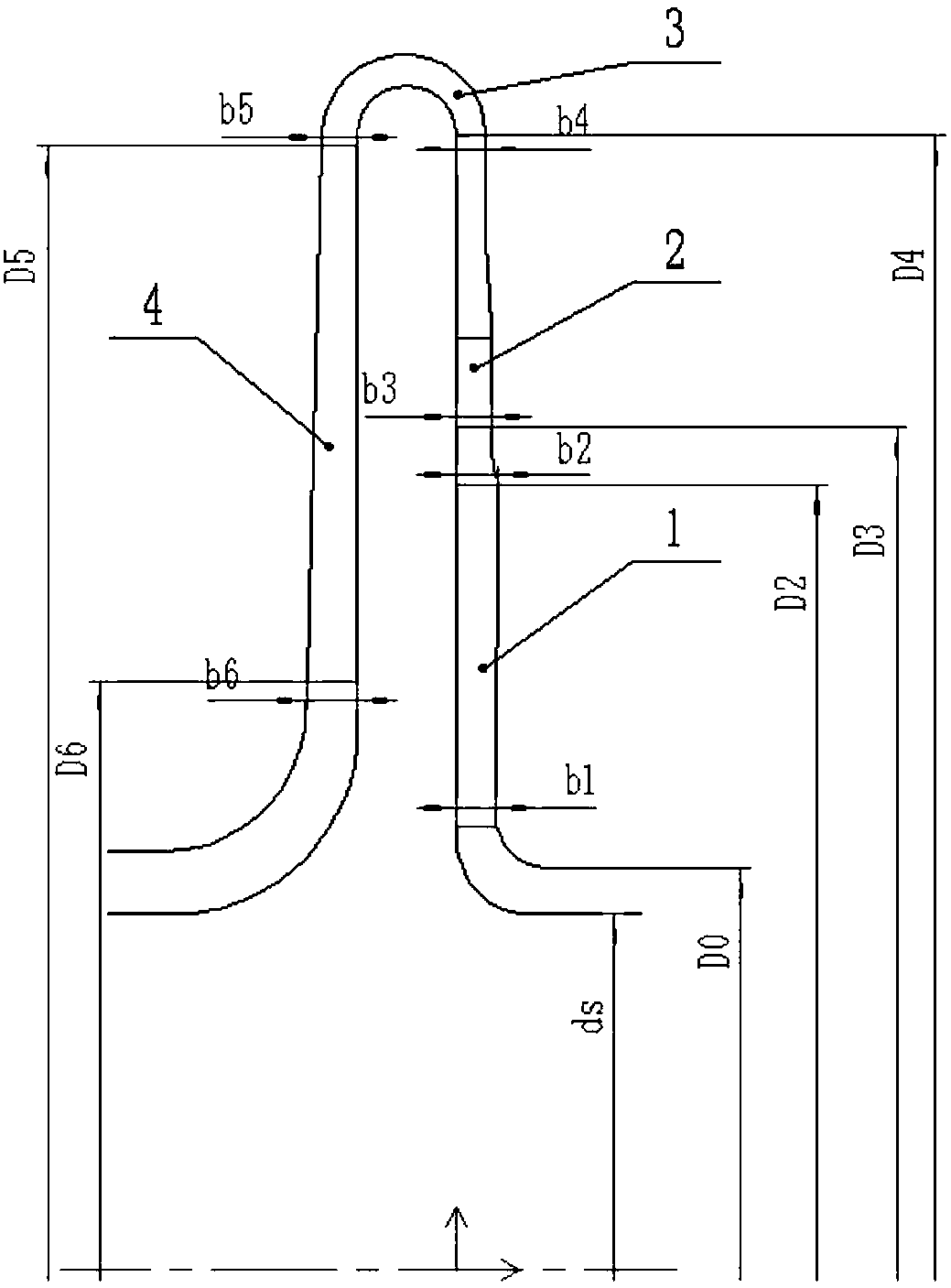
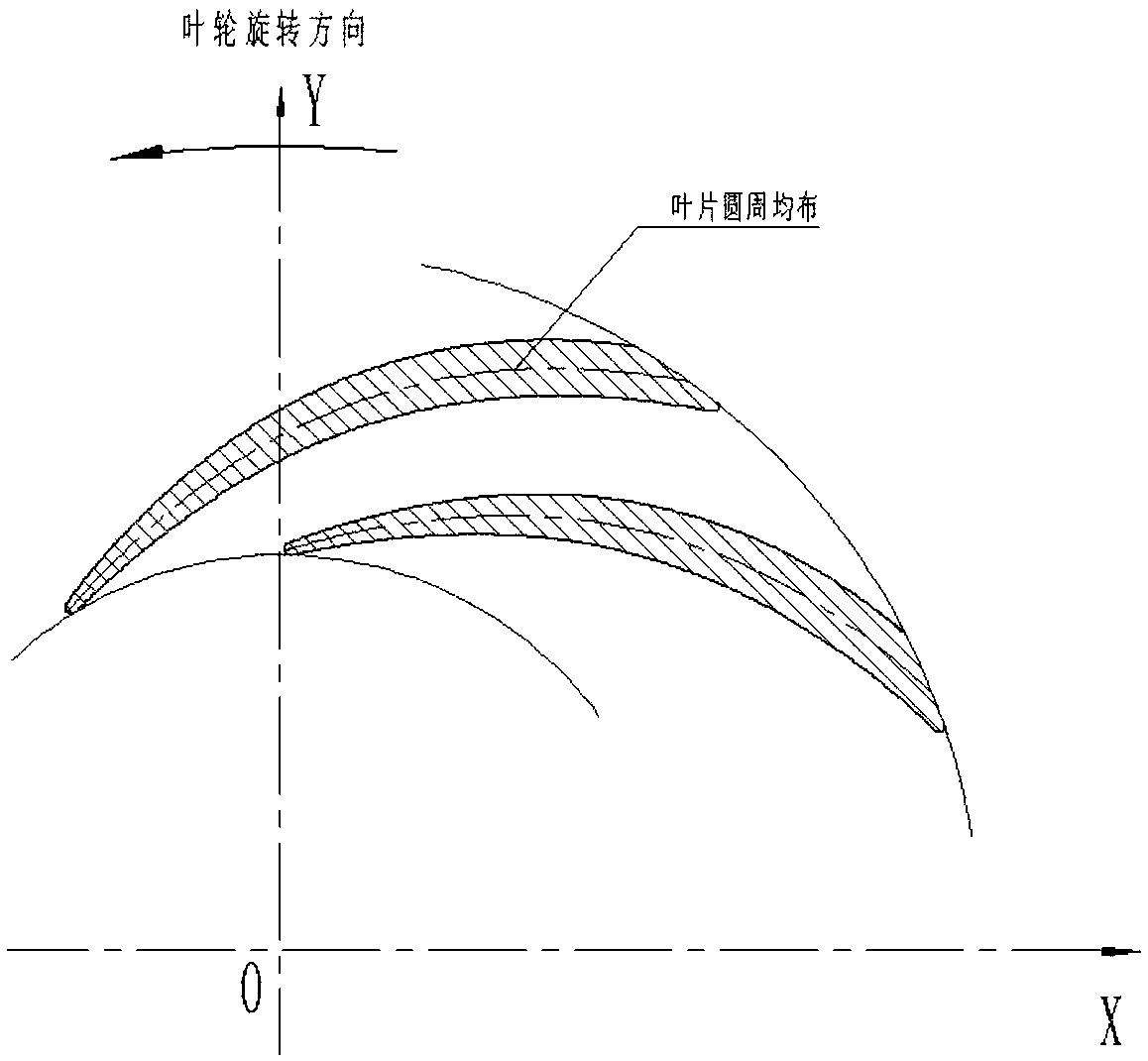
[0048] In order to solve the above problems, the embodiment of the present invention provides a uniaxial CO with a flow coefficient of 0.0086 2 Compressor end stage model stage for single shaft CO 2 Modular design of compressor products, such as figure 1 As shown, the model stage is located in the compressor, including impeller 1, vane diffuser 2, bend 3 and reflux device 4, wherein the impeller 1 is a low-friction wedge-shaped im...

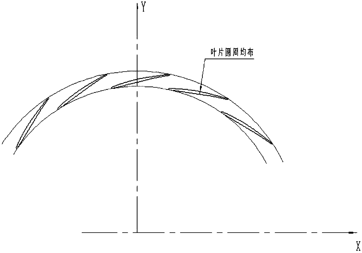

PUM


Abstract

The invention discloses a single-shaft CO2 compressor final-section model stage with a flow coefficient of 0.0086 and an impeller design method, and mainly aims to improve the efficiency of a CO2 compressor set, to reduce the power consumption of the CO2 compressor set, to guarantee wider working condition range of compressors and to improve stability of rotors. The model stage comprises an impeller, a blade diffuser, a curve and a reflux machine, wherein the impeller is a low-friction wedged impeller designed according to specific blade thickness reference rules, and is positioned in an inletposition of the model stage; the blade diffuser is arranged in an outlet of the impeller; the reflux machine is positioned in an outlet position of the model stage; the blade diffuser and the refluxmachine communicate through the curve; the machine mach number Mu2 of the model stage is 0.6-0.9; the flow coefficient phi 1 is 0.0086; the design point energy head coefficient t is 0.62; each mach number lower polytropic efficiency npol is 0.68-0.685; and the applied flow range is 73-139% of the design point.

Description

technical field [0001] The invention relates to the field of model-level design, in particular to a uniaxial CO with a flow coefficient of 0.0086 2 Model stage and impeller design method of the last stage of compressor. Background technique [0002] The development of modern centrifugal compressors is mostly based on user needs, based on the existing model-level database, and uses similarity theory to design schemes. Therefore, the pros and cons of model-level design directly affect the performance of the entire product. As an important part of the urea synthesis plant, CO 2 Because of the characteristics of high pressure and high density of working medium, the compressor unit has become one of the most technical and most important products of major compressor manufacturers. [0003] Currently, CO 2 The flow coefficients of the stages behind the high-pressure cylinder of the compressor are very small, and some flow coefficients Φ 1 It can even go to 0.004 or lower. How...

Claims


Application Information

Patent Timeline
IPC IPC(8): F04D29/28G06F17/50
CPCF04D29/284F05D2260/81G06F30/17G06F30/20
Inventor 谭佳健杨树华孙玉莹刘长胜杜俊杰张宏伟
Owner SHENYANG TURBO MASCH CORP
Learn More