
Belt transmission structure and massage manipulator

A technology of belt transmission and manipulator, which is applied in the direction of vibration massage, kneading massage equipment, massage auxiliary products, etc., can solve the problems of overuse and inability to share gearboxes, etc., and achieve the effect of saving space, compact structure and fewer parts

Pending Publication Date: 2018-06-19
林学金
View PDF8 Cites 0 Cited by
  • Summary
  • Abstract
  • Description
  • Claims
  • Application Information

AI Technical Summary

Problems solved by technology

The reason is that the kneading manipulator needs to move slowly, which is completed by worm gear deceleration, while the tapping action requires high-speed rotation, and the two cannot share a set of gearboxes. Furthermore, the space constraints cannot be achieved by complex transmission relationships. over

Method used


Image

  • Belt transmission structure and massage manipulator
  • Belt transmission structure and massage manipulator
  • Belt transmission structure and massage manipulator

Examples


Embodiment Construction

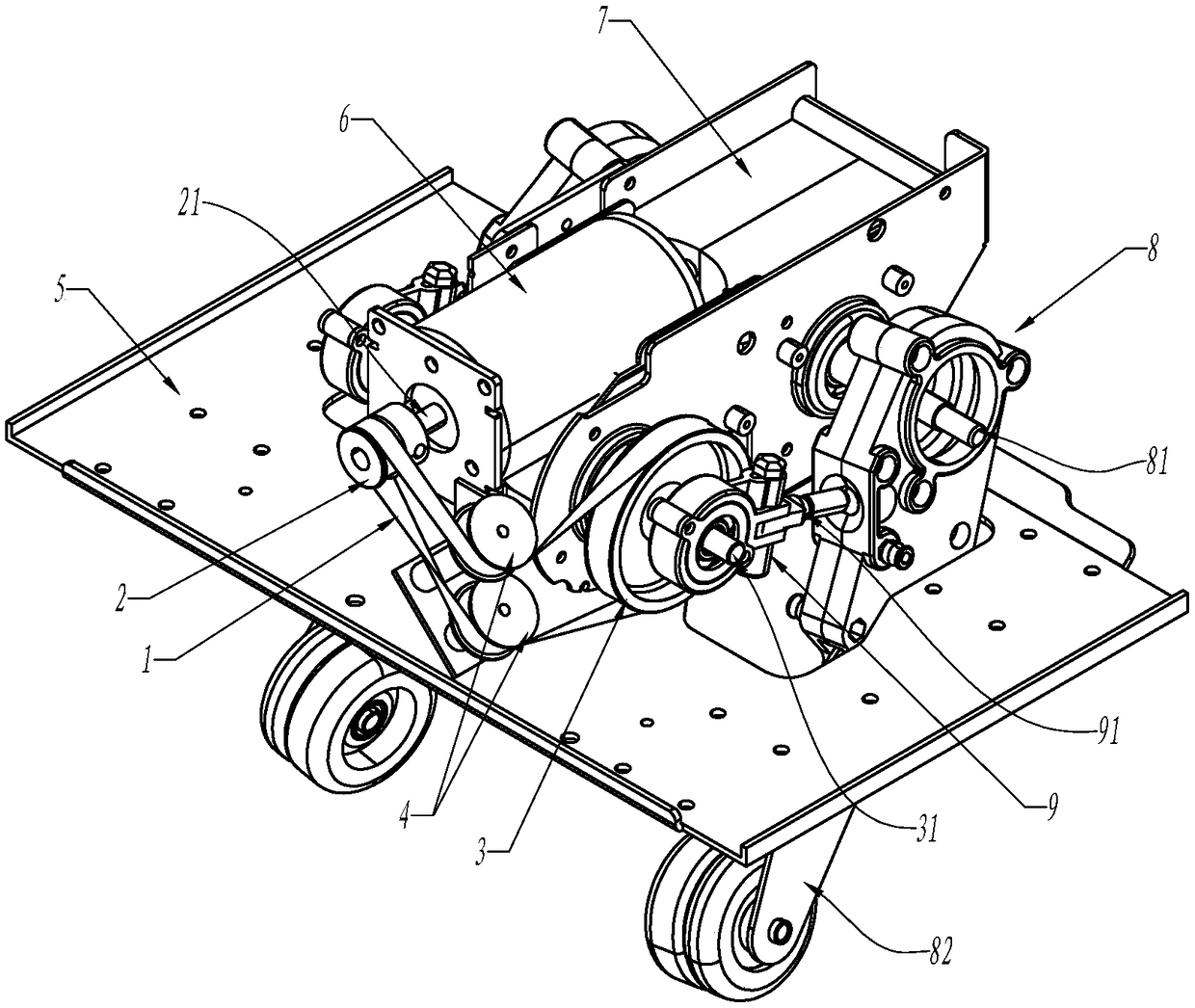
[0025] refer to figure 1 and figure 2 , is the example of the application of the transmission belt on the massage manipulator, with the help of the transmission belt 1 around the corner of the motor, and forms a transmission connection with the percussion shaft, that is, the driven shaft 31.

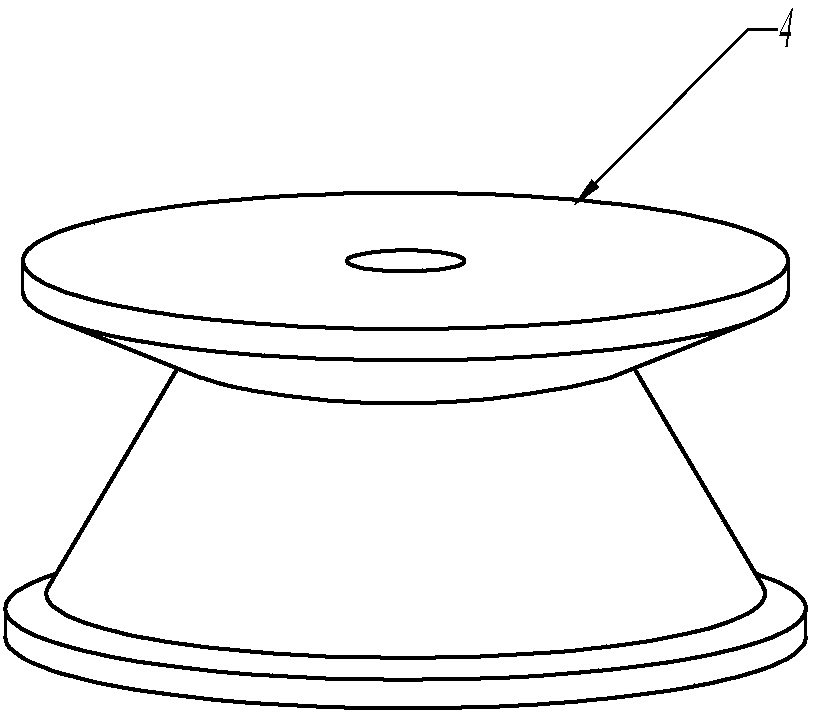
[0026] The belt transmission structure includes a transmission belt 1, a driving wheel 2, a driven wheel 3 and two transition wheels 4; the driving wheel 2 is locked on the driving shaft 21, that is, the output shaft of the motor, and is connected to power; the driven wheel 3 is locked on the On the driven shaft 31, this example is the tapping shaft; and the other end of the output shaft of the motor drives the manipulator 82 to move through the worm gear box.

[0027] The two transition wheels 4 are installed at the intersection corners of the driving wheel 2 and the driven wheel 3 tangent planes, and the two tangent lines passing through the degree wheel 4 are correspondingly tangent...


PUM


Abstract

The invention relates to a belt transmission structure and a massage manipulator. The belt transmission structure comprises a driving wheel fixedly locked on a driving shaft, a driven wheel fixedly locked on a driven shaft and a transmission belt; the belt transmission structure further comprises two transition wheels, the two transition wheels are mounted at the tangent plane cross corner of thedriving wheel and the driven wheel, and two tangent lines passing through the transition wheels are correspondingly tangent to the driving wheel and the driven wheel; the transmission belt is sleevedbetween the driving wheel and the driven wheel, and the middle section can bypass the transition wheels to change the direction; the massage manipulator uses the belt transmission structure to transmit the motor power which drives a kneading assembly to a rapping assembly, so that one motor drives both the kneading action and rapping additional action. According to the belt transmission structureand the massage manipulator, the two transition wheels installed between the driving shaft and the driven wheel are cleverly utilized, so that one transmission belt can bypass the two transition wheels to form a turning transmission between the driving wheel and the driven wheel, few parts are arranged by bypassing the motor point location, space is saved, and an option for turning transmission isprovided.

Description

Technical field: [0001] The invention relates to a belt transmission structure and a massage manipulator, in particular to a single-belt turning transmission structure, which realizes the massage manipulator with tapping action added to a single motor. Background technique: [0002] Belt transmission is a very common transmission method. A single transmission belt can be used to form the following three classic transmission structures: split transmission, cross transmission and semi-cross transmission. These transmission structures are suitable for the environment where there is no equipment blocking between the driving wheel and the driven wheel. If there is an obstacle between the driving wheel and the driven wheel, it needs to be realized with the help of two transmission belts, which not only takes up space, but also increases maintenance costs. Applied on high-end equipment, especially in the field of massagers. [0003] For example, massage manipulators with tapping f...

Claims


Application Information

Patent Timeline
IPC IPC(8): A61H7/00A61H23/02
CPCA61H7/007A61H23/006A61H23/02A61H2201/1207A61H2201/1659
Inventor 林学金
Owner 林学金
Learn More