
Optimal configuration method for fault current limiters

A technology of fault current limiter and optimized configuration, which is applied in the direction of emergency protection circuit devices, circuit devices, AC network circuits, etc. for limiting overcurrent/overvoltage, and can solve the problem of incomplete consideration of fault factors and influence on power system stability , unable to suppress problems such as multi-infeed DC commutation failure, to meet the requirements of safe and stable operation and achieve the effect of large economic benefits

Inactive Publication Date: 2018-06-15
NARI TECH CO LTD +3
View PDF2 Cites 16 Cited by
  • Summary
  • Abstract
  • Description
  • Claims
  • Application Information

AI Technical Summary

Problems solved by technology

[0004] The purpose of the present invention is to overcome the deficiencies in the prior art, provide an optimal configuration method for the fault current limiter, and solve the problem that the fault factors in the optimal configuration method for the fault current limiter in the prior art are not fully considered and cannot suppress the multi-infeed DC converter. phase failures, technical issues affecting power system stability

Method used


Image

  • Optimal configuration method for fault current limiters
  • Optimal configuration method for fault current limiters
  • Optimal configuration method for fault current limiters

Examples


Embodiment Construction

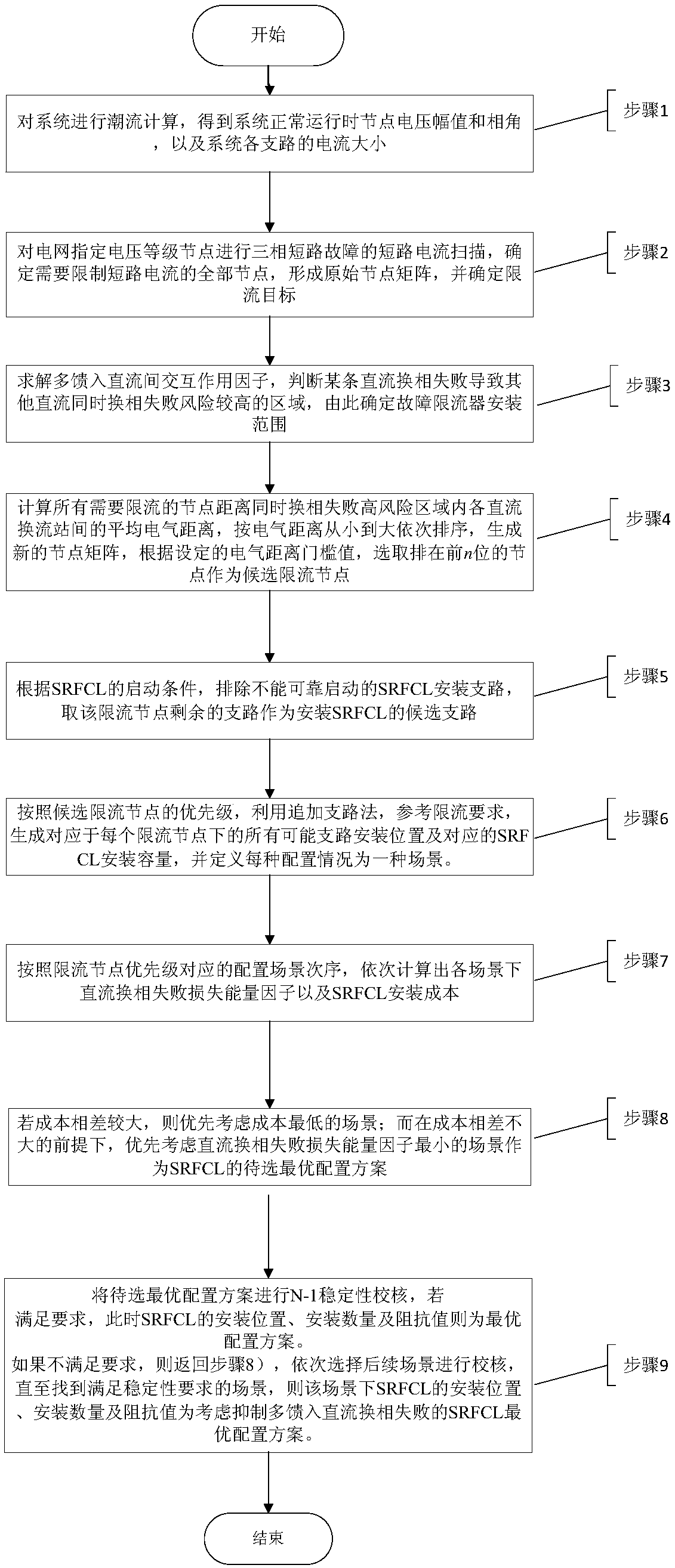
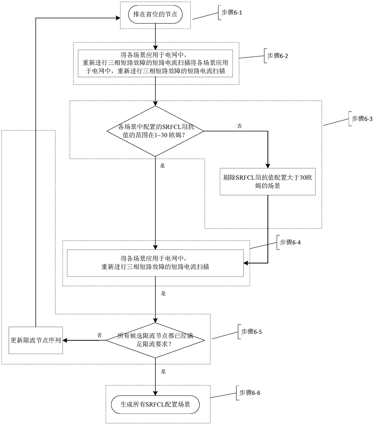
[0043] The present invention provides a method for optimizing configuration of a fault current limiter, specifically providing a method for optimizing configuration of a series resonant type fault current limiter (Series Ressonant Type Fault Current Limiter, hereinafter referred to as SRFCL), including: determining the installation of the SRFCL Scope, according to the requirements of current limitation, use branch addition method to form configuration scenarios generated by SRFCL installation quantity, installation location and installation capacity, consider the suppression effect of SRFCL on DC commutation failure, and screen the optimal configuration scheme of SRFCL to be selected. The optimal configuration scheme is checked for power grid transient stability, and the optimal configuration scheme of SRFCL is finally determined. The present invention is beneficial to electric power system planning and operation personnel when formulating the optimal configuration scheme of th...


PUM


Abstract

The invention discloses an optimal configuration method for fault current limiters. An area with high risk of failure in simultaneous phase commutation is judged by using a multi-infeed DC interactionfactor. During the configuration of an SRFCL device, the average electrical distance from a current limiting node to the DC converter stations in the area with high risk of failure in simultaneous phase commutation is calculated, and the priority of the current limiting node is determined to avoid large-range search. Meanwhile, the suppression effect of SRFCL on DC commutation failure is considered. Therefore, an SRFCL optimal configuration scheme taking both short-circuit current limiting and commutation failure suppressing into account is realized. The method is helpful for power system planners to grasp the influence of SRFCL installation and configuration on the phase commutation failure of a multi-infeed DC system and visually determine an SRFCL installation area. The indexes in thearea can be displayed in order during calculation. The method is easy to implement. Decision support is provided for the optimal configuration method of SRFCL in the multi-infeed DC system.

Description

technical field [0001] The invention relates to an optimal configuration method of a fault current limiter, which belongs to the technical field of power systems and automation thereof. Background technique [0002] In response to the increasing short-circuit current level of the system, the fault current limiter has an impedance close to zero during normal operation and has no adverse effects on the power grid. When a short-circuit fault occurs in the power grid, the impedance quickly increases to limit the short-circuit current, thereby ensuring that the circuit breaker can reliably cut off the fault. The circuit and other characteristics have become a new type of short-circuit current limiting device that has been studied more. However, due to the high cost of the ultra-high voltage fault current limiter, the optimal configuration of the fault current limiter has become a research hotspot. However, in the load center area, not only the problem of excessive short-circuit ...

Claims


Application Information

Patent Timeline
IPC IPC(8): H02J3/00H02H9/02
CPCH02H9/02H02J3/00H02J2203/20
Inventor 崔晓丹李熙李威吕亚洲李碧君方勇杰郄朝辉吴兴扬李兆伟薛峰李海峰姚建国刘前卫
Owner NARI TECH CO LTD
Learn More