
Cable stranding machine with multistage stranding structure

A stranding machine and cable technology, which is applied in the direction of cable/conductor manufacturing, circuits, electrical components, etc., can solve the problems of high friction between cables and through holes, cable wear, and large bending angles, so as to ensure the quality of finished products and improve the use of Long life, reasonable design effect

Inactive Publication Date: 2018-06-15
江阴市华伟机械制造有限公司
View PDF4 Cites 13 Cited by
  • Summary
  • Abstract
  • Description
  • Claims
  • Application Information

AI Technical Summary

Problems solved by technology

At present, the stranding machines on the market have the following problems in production and use: the cables to be twisted are generally wound on the winding wheel, and the winding wheel is set on the large disc. Due to the large diameter of the large disc, the winding The wheel is generally set on the edge of the large disc, so the angle of the cable from the winding wheel to the through hole on the twisting reel is relatively large, resulting in a large friction between the cable and the through hole, which may cause the cable to wear before twisting; When the cable passes through the through hole, it will vibrate, resulting in high friction between the cable and the through hole of the winch reel, and the through holes of the cable and the winch reel are worn to varying degrees, which affects the service life of the winch reel. Affect the quality of the finished cable

Method used

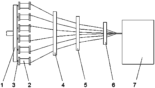
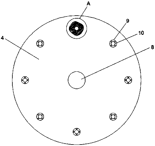
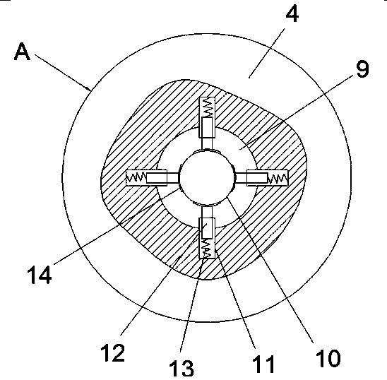

Image

  • Cable stranding machine with multistage stranding structure
  • Cable stranding machine with multistage stranding structure
  • Cable stranding machine with multistage stranding structure

Examples


Embodiment Construction

[0014] The present invention is described in further detail now in conjunction with accompanying drawing. These drawings are all simplified schematic diagrams, which only illustrate the basic structure of the present invention in a schematic manner, so they only show the configurations related to the present invention.

[0015] like Figure 1-3 As shown, the present invention is a cable stranding machine with a multi-stage stranding structure, including a vertically arranged disc 1, on which a number of winding wheels 2 evenly distributed in the circumferential direction are arranged, and the winding The wheel 2 is connected to the disk 1 through the rotating shaft 3, and one side of the disk 1 is provided with a first-level winch 4, a second-level winch 5 and a third-level winch 6 in sequence, and the third-level winch 6 is far away from the disc 1 One side of the wire mold base 7 is provided, the diameter of the first-level winch 4 > the diameter of the second-level winch 5...


PUM


Abstract

The invention discloses a cable stranding machine with a multistage stranding structure, comprising a vertical disc. The disc is provided with a plurality of winding wheels uniformly distributed on the circumference. The winding wheels are connected with the disc through rotating shafts. A first-stage winch, a second-stage winch and a third-stage winch are arranged in turn on one side of the disc.A line die holder is arranged on one side of the third-stage winch away from the disc. The cable stranding machine is reasonable in design. Because of the setting of the multiple stages of winches, the broken lines of cables from the winding wheels to the line die holder are smooth, and large friction caused by large break angles of the cables is prevented. The cables apply pressure to lantern rings in multiple directions when shaking. The friction between the cables and the lantern rings is reduced as the pressure is absorbed in the compression and elongation process of springs, and therefore, the wear between the lantern rings and the winches is reduced. In conclusion, the wear between the cables and the winches is reduced, the wear of the through holes of the winches is reduced, the service life of the winches is prolonged, and the quality of finished cables is ensured.

Description

technical field [0001] The invention relates to the field of cable production equipment, in particular to a cable stranding machine with a multi-stage stranding structure. Background technique [0002] The twisting machine is an important cable production equipment, including the twisting reel and cable forming equipment. During production, the multi-strand cables are passed through multiple through holes on the upper side of the twisting reel. Multi-strand wires with through-holes are twisted into a single cable. At present, the stranding machines on the market have the following problems in production and use: the cables to be twisted are generally wound on the winding wheel, and the winding wheel is set on the large disc. Due to the large diameter of the large disc, the winding The wheel is generally set on the edge of the large disc, so the angle of the cable from the winding wheel to the through hole on the twisting reel is relatively large, resulting in a large fricti...

Claims


Application Information

Patent Timeline
IPC IPC(8): H01B13/02
CPCH01B13/0257H01B13/0207
Inventor 高伟
Owner 江阴市华伟机械制造有限公司
Learn More