
Cement utility pole moving and mounting device for electric power engineering

A technology of cement utility poles and electric power engineering, applied in the field of electric power engineering, can solve problems such as time-consuming and labor-intensive safety hazards, and achieve the effects of low safety hazards, strong practicability, and easy access

Inactive Publication Date: 2018-06-15
彭素珍
View PDF6 Cites 1 Cited by
  • Summary
  • Abstract
  • Description
  • Claims
  • Application Information

AI Technical Summary

Problems solved by technology

[0002] At present, in electric power engineering sites, in order to achieve long-distance power output, some cement power poles will be set up in some villages. When the cement power poles are placed, the staff first needs to dig out holes in the ground, and then the personnel are required to erect the power cement poles. Inserting into the cavity requires a special mechanism when inserting, and the existing equipment needs to remove the pole from the mobile device and then place it on the installation device before it can work. The whole process is time-consuming and labor-intensive and has high potential safety hazards

Method used

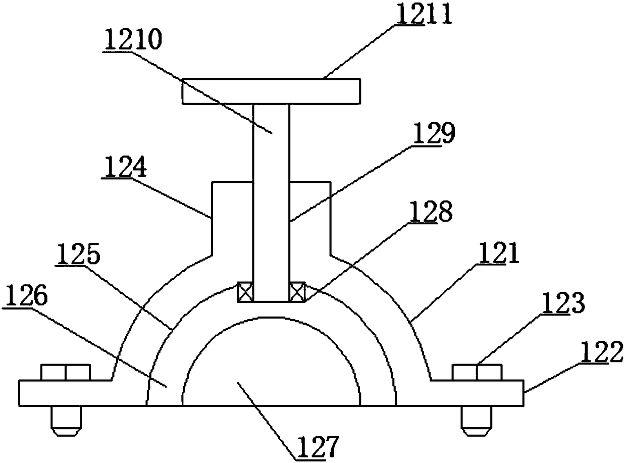
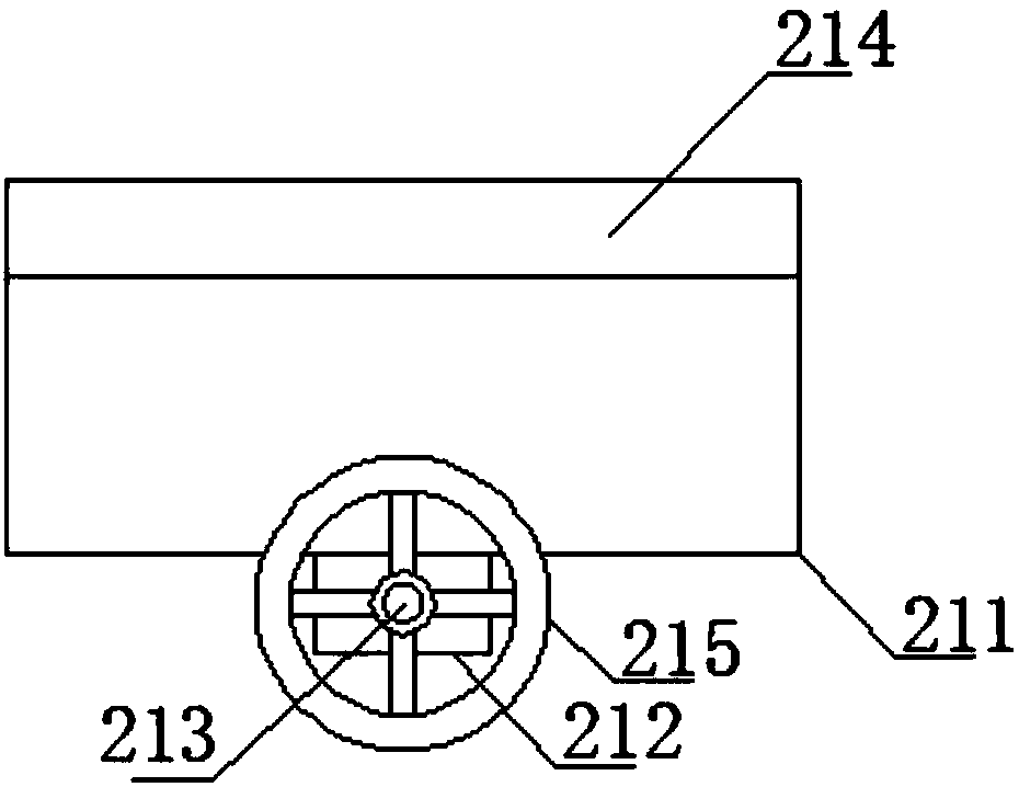

Image

  • Cement utility pole moving and mounting device for electric power engineering
  • Cement utility pole moving and mounting device for electric power engineering
  • Cement utility pole moving and mounting device for electric power engineering

Examples


Embodiment Construction

[0017] The following will clearly and completely describe the technical solutions in the embodiments of the present invention with reference to the accompanying drawings in the embodiments of the present invention. Obviously, the described embodiments are only some, not all, embodiments of the present invention. Based on the embodiments of the present invention, all other embodiments obtained by persons of ordinary skill in the art without making creative efforts belong to the protection scope of the present invention.

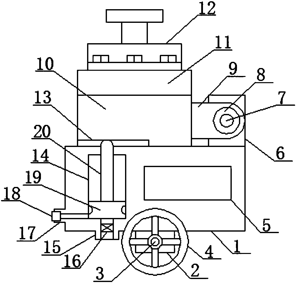
[0018] see figure 1 , an embodiment provided by the present invention: comprising a main moving rectangular block 1 and a moving mechanism for placing the top of a cement utility pole, the bottom center of the main moving rectangular block 1 is provided with two opposite main vertical boards 2, and the two main vertical The center of the plate 2 is equipped with a main rotating shaft 3 through bearings, and a main roller 4 is installed at the two ends of the t...


PUM


Abstract

The invention discloses a cement utility pole moving and mounting device for electric power engineering. The cement utility pole moving and mounting device comprises a main moving rectangular block and a cement utility pole top end placing and moving mechanism; two opposite main vertical plates are arranged at the center of the bottom of the main moving rectangular block, and main rotating shaftsare mounted on the center portions of the two main vertical plates through bearings; two main idler wheels are separately installed at both ends of the main rotating shafts, and a tool placing grooveis formed in the main moving rectangular block, and the center of the inner part of the main moving rectangular block is provided with a flex space; and the bottom of the main moving rectangular blockis provided with a main air inlet pipeline with is integrated with the main moving rectangular block, and the main air inlet pipeline communicates with the bottom of the flex space. According to thecement utility pole moving and mounting device for the electric power engineering, not only can a cement utility pole be transported, but also the installation work can be performed on the cement utility pole; air pressure is used for the telescopic work, so that the characteristics of low raw material cost and convenient access are achieved; in addition, the cement utility pole moving and mounting device is provided with a power pole fixing and control mechanism which can effectively control the movement state of a power pole, so that the security risk is low, and the practicability is high.

Description

technical field [0001] The invention relates to the technical field of electric power engineering, in particular to a mobile installation device for cement utility poles used in electric power engineering. Background technique [0002] At present, in electric power engineering sites, in order to achieve long-distance power output, some cement power poles will be set up in some villages. When the cement power poles are placed, the staff first needs to dig out holes in the ground, and then the personnel are required to erect the power cement poles. Inserting into the cavity requires a special mechanism when inserting, and the existing equipment needs to remove the pole from the mobile device and then place it on the installation device before it can work. The whole process is time-consuming and labor-intensive and has high potential safety hazards . Contents of the invention [0003] The object of the present invention is to provide a mobile installation device for cement u...

Claims


Application Information

Patent Timeline
Patent Type & Authority Applications(China)
IPC IPC(8): E04H12/00E04H12/34
CPCE04H12/00E04H12/34
Inventor 彭素珍
Owner 彭素珍
Learn More