
Concrete quantified mixing device

A quantitative mixing and concrete technology, used in mixing operation control devices, clay preparation devices, mixing operation control and other directions, can solve the problems of increasing material proportioning time, inability to weigh, affecting work efficiency, etc., to ensure the delivery rate, reduce Matching time and improving work efficiency

Inactive Publication Date: 2018-06-15
张志通
View PDF0 Cites 12 Cited by
  • Summary
  • Abstract
  • Description
  • Claims
  • Application Information

AI Technical Summary

Problems solved by technology

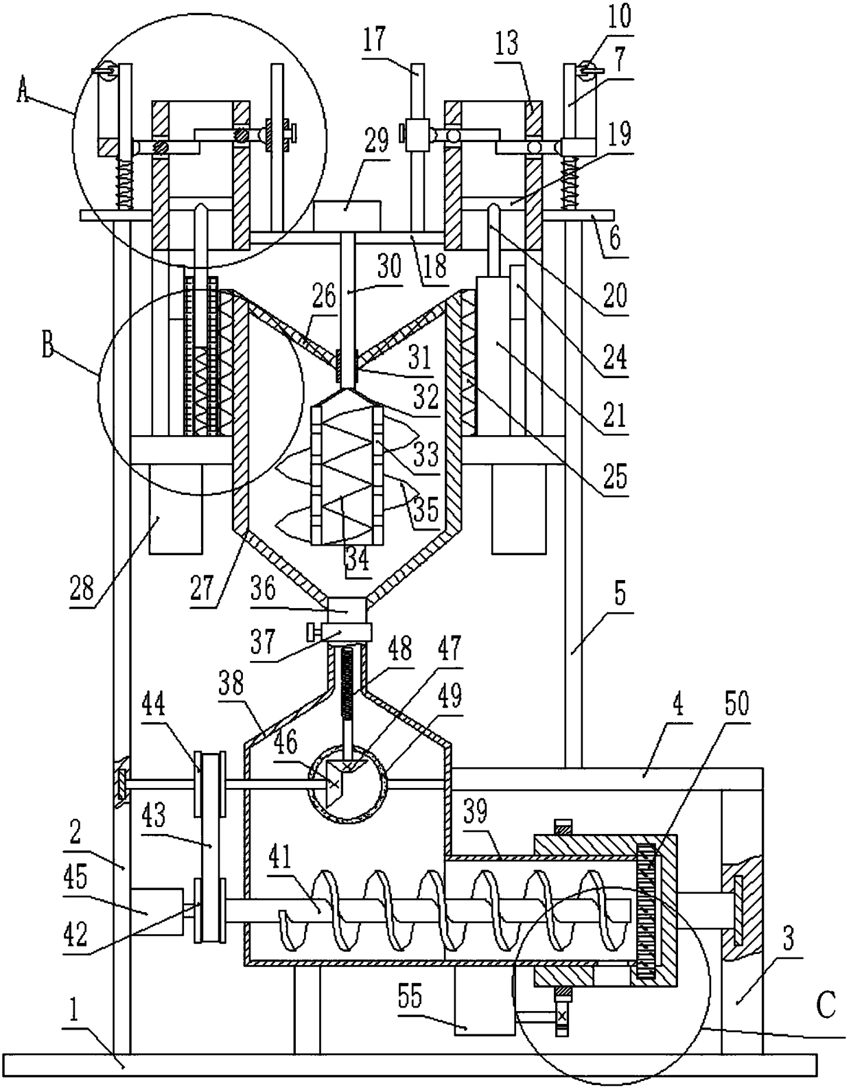
[0002] When traditional quantitative batching and mixing of concrete, the weighing mechanism generally needs to include three pipelines, batching scales and transfer bins. The batching scale can only weigh the materials in one pipeline at a time, and then pour the materials into the transfer bin before continuing. To weigh the materials in another pipeline, this batching weighing mechanism cannot weigh the materials in each pipeline at the same time, which increases the material proportioning time and seriously affects the work efficiency, and during the mixing process, the motor drives The stirring shaft rotates, and the rotation of the stirring shaft drives the first-stage stirring blade, the second-stage stirring blade, and the third-stage stirring blade to rotate. The stirring of the concrete is only carried out by the mechanical force of the stirring blade. The concrete near the stirring blade is more stressed and easy to stir. Uniform, the concrete away from the mixing blade is under less force, and it is not easy to be mixed evenly

Method used


Image

  • Concrete quantified mixing device
  • Concrete quantified mixing device
  • Concrete quantified mixing device

Examples


Embodiment Construction

[0020] Below in conjunction with accompanying drawing and specific embodiment the present invention is described in further detail:

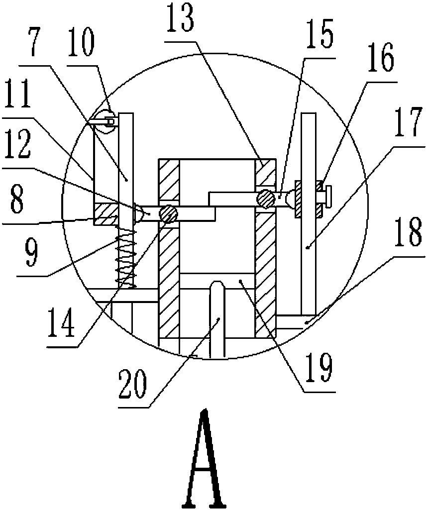
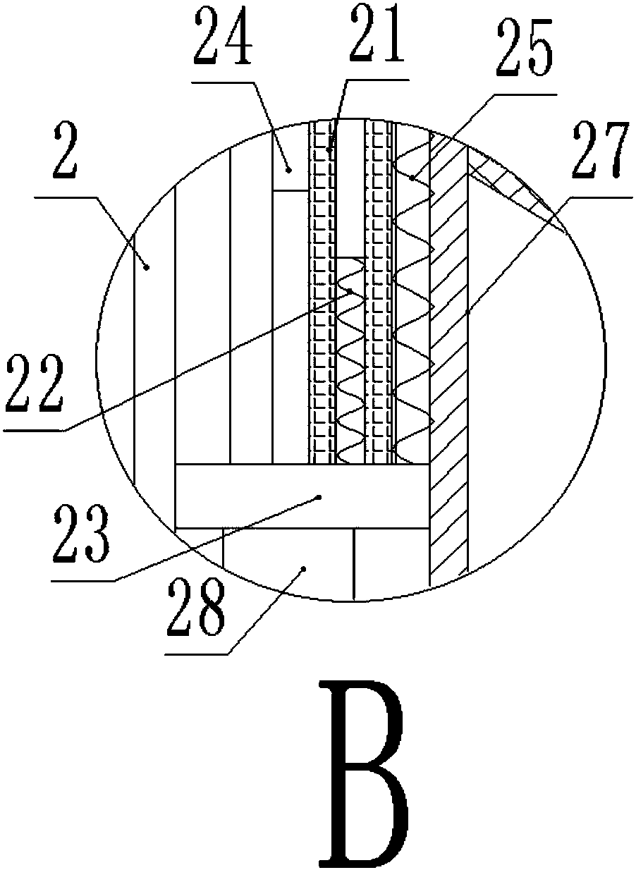
[0021] Such as figure 1 , figure 2 , image 3 , Figure 4 , Figure 5 , Image 6As shown, a concrete quantitative mixing device includes a base 1, and the top of the base 1 is fixedly provided with a support bar A2 and a support bar B3, and the top of the support bar B3 is fixedly connected with a fixed cross bar 4, and the fixed cross bar 4 A support rod C5 is fixedly connected to the top, a support plate 6 is fixedly connected to the top of the support rod A2 and the support rod C5, a fixed vertical rod A7 is connected to the support plate 6, and a sleeve is slidably connected to the fixed vertical rod A7 A8, a tension spring 9 is fixed between the sleeve A8 and the support plate 6, and the tension spring 9 is set on the fixed vertical bar A7, and a steel wire 11 is fixedly connected to one side of the sleeve A8, and the steel wire 11 T...


PUM


Abstract

The invention discloses a concrete quantified mixing device which comprises a base. A supporting rod A and a supporting rod B are fixedly arranged at the top of the base. The top end of the supportingrod B is fixedly connected with a fixed transverse rod. The top end of the fixed transverse rod is fixedly connected with a supporting rod C. The top end of the supporting rod A and the top end of the supporting rod C are fixedly connected with supporting plates. A fixed vertical rod A is connected to each supporting plate. In the design, through rotating control of two striker plates, the rate of adding concrete raw materials can be controlled, and therefore it is guaranteed that the needed raw material quantity can be grasped; through the interaction of weighing plates and shrinkage springs, the quantity of concrete added into a stirring barrel can be controlled more precisely, and therefore quantified mixing is effectively achieved, and the matching time is reduced; and through rotation of two blades different in spiral direction, the concrete on the upper portion in the stirring barrel can be conveyed downwards, the concrete on the lower portion in the stirring barrel can be conveyed upwards, the concrete cyclically flows in the stirring barrel, and the effect of uniform concrete mixing is achieved.

Description

technical field [0001] The invention relates to the field of a concrete quantitative mixing device, in particular to a concrete quantitative mixing device. Background technique [0002] When traditional quantitative batching and mixing of concrete, the weighing mechanism generally needs to include three pipelines, batching scales and transfer bins. The batching scale can only weigh the materials in one pipeline at a time, and then pour the materials into the transfer bin before continuing. To weigh the materials in another pipeline, this batching weighing mechanism cannot weigh the materials in each pipeline at the same time, which increases the material proportioning time and seriously affects the work efficiency, and during the mixing process, the motor drives The stirring shaft rotates, and the rotation of the stirring shaft drives the first-stage stirring blade, the second-stage stirring blade, and the third-stage stirring blade to rotate. The stirring of the concrete is...

Claims


Application Information

Patent Timeline
IPC IPC(8): B28C7/04
CPCB28C7/0422
Inventor 张志通
Owner 张志通
Learn More