
Polarization tracking device

A technology of polarization tracking and circular polarization, applied in the direction of electrical components, antennas, etc., can solve the problems of failure to achieve polarization control, high gain, low profile, etc., and achieve the effect of small loss, low loss and simple structure

Active Publication Date: 2018-06-12
苏州灵致科技有限公司
View PDF6 Cites 12 Cited by
  • Summary
  • Abstract
  • Description
  • Claims
  • Application Information

AI Technical Summary

Problems solved by technology

[0006] The Chinese patent application number 201611057972.X discloses a sub-array fed VICTS satellite antenna, which provides a satellite antenna with low profile, high gain, large beam scanning angle and strong radiation capability, but the same Failure to achieve polarization control

Method used


Image

  • Polarization tracking device
  • Polarization tracking device
  • Polarization tracking device

Examples


Embodiment Construction

[0036] In the following description, many technical details are proposed in order to enable readers to better understand the application. However, those skilled in the art can understand that the technical solutions claimed in this application can be realized even without these technical details and various changes and modifications based on the following implementation modes.

[0037] In order to make the purpose, technical solution and advantages of the present invention clearer, the following will further describe the implementation of the present invention in detail in conjunction with the accompanying drawings.

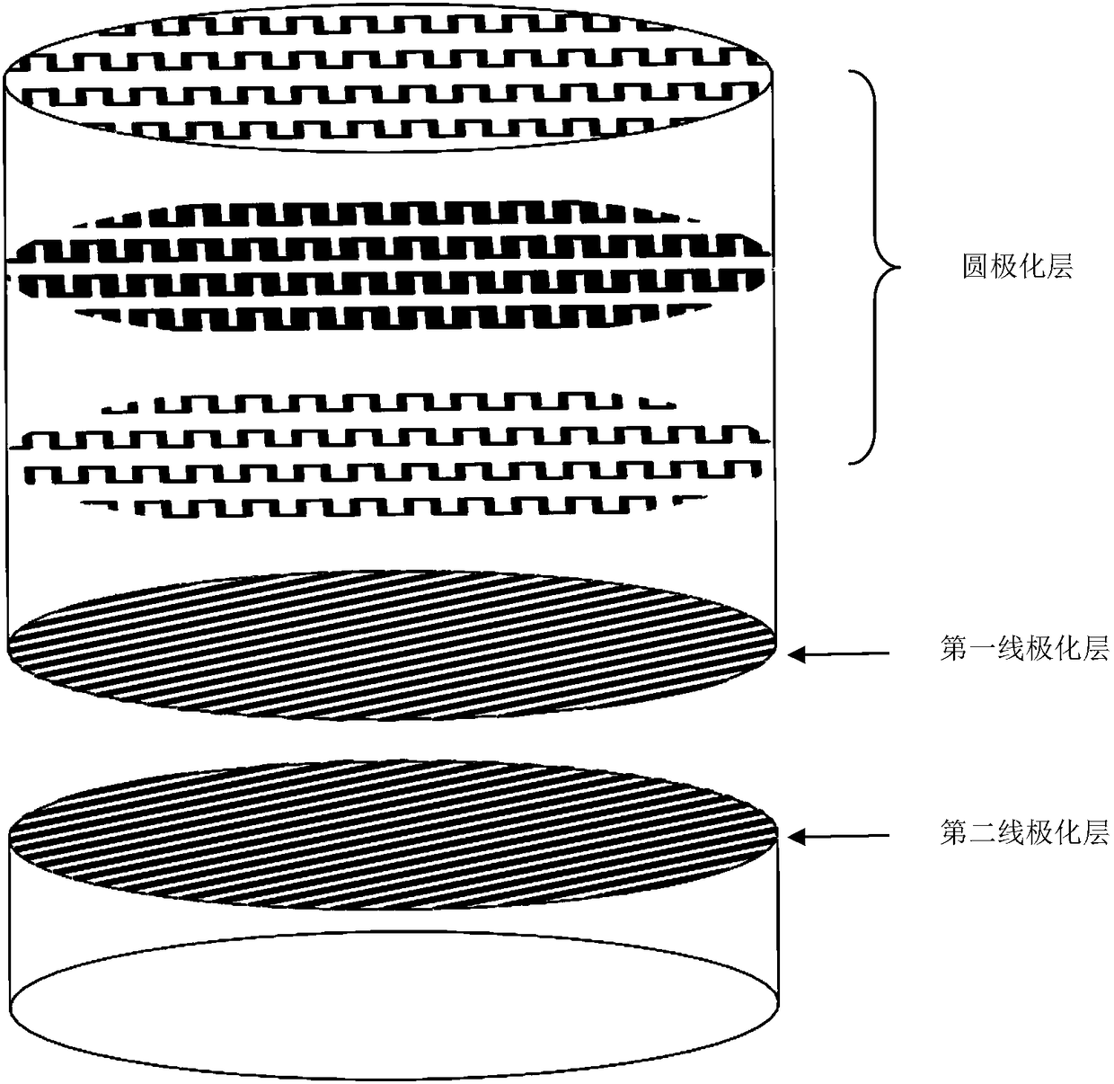
[0038] The embodiment of the present application relates to a polarization tracking device, figure 1 It is a structural diagram of a polarization tracking device in the present invention. Such as figure 1 As shown, the polarization tracking device includes a first rotating structure and a second rotating structure, the first rotating structure includes a first ...


PUM


Abstract

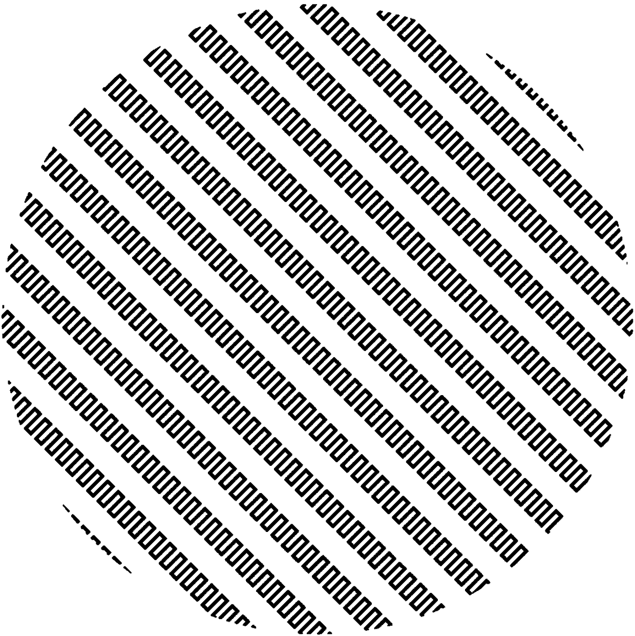
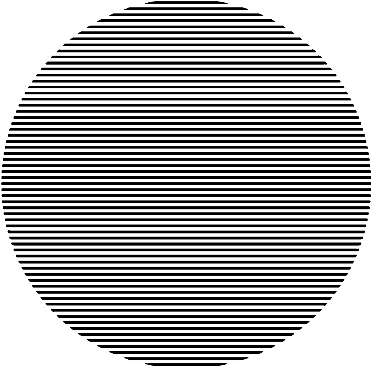
The invention relates to an antenna field, and discloses a polarization tracking device. The polarization tracking device comprises a first rotary structure and a second rotary structure; the first rotary structure comprises a first linear polarization layer and at least three circularly polarized layers; the first linear polarization layer is coaxially arranged beneath at least three circularly polarized layers, the grid direction of every circularly polarized layer is the same; the first linear polarization layer is a plane wire grating polarizer, the included angle between the grid direction of the plane wire grating polarizer and the grid direction of every circularly polarized layer is 45 degrees; the second rotating structure comprises a second linear polarization layer and an antenna radiation port; the second linear polarization layer is arranged at the upper part of the antenna radiation port at the gamma g / 2 space; the first rotating structure is coaxially arranged at the upper part of the second rotating structure, and relatively rotated by the same axial core. The polarization tracking device is simple in structure, low in loss, and able to accurately track the satellite polarization direction.

Description

technical field [0001] The invention relates to the field of antennas, in particular to a polarization tracking device. Background technique [0002] The beam scanning antenna is an antenna or antenna array with high gain performance. This type of antenna itself has high directional radiation characteristics. At the same time, by changing the working mode, working state, working frequency or antenna attitude of the antenna, the The direction of maximum radiation changes, enabling beam scanning. Beam scanning antennas are used in a wide variety of applications, especially in military and scientific research. Military radar, scientific research detection equipment, and antenna equipment used in systems that require satellite navigation and positioning must have beam scanning characteristics. [0003] As the popularity of phased array antennas gradually increases, their applications in the field of satellite communications are also increasing. Phased array antennas have the ...

Claims


Application Information

Patent Timeline
Patent Type & Authority Applications(China)
IPC IPC(8): H01Q15/24
CPCH01Q15/24
Inventor 黄季甫李东晓尤清春秦丽婷尤阳
Owner 苏州灵致科技有限公司
Learn More