
Glass cover plate component, 3D display device and manufacturing method

A glass cover and component technology, applied in the direction of optical components, optics, instruments, etc., can solve problems affecting module touch function, failure, etc.

Inactive Publication Date: 2018-06-12
FUTURE TECH XIANG YANG CO LTD
View PDF9 Cites 2 Cited by
  • Summary
  • Abstract
  • Description
  • Claims
  • Application Information

AI Technical Summary

Problems solved by technology

[0003] However, after the 3D optical device is bonded to the display, multiple layers of media are added between the glass cover and the touch layer inside the display, which will inevitably affect the touch function of the module or even make it invalid

Method used


Image

  • Glass cover plate component, 3D display device and manufacturing method
  • Glass cover plate component, 3D display device and manufacturing method
  • Glass cover plate component, 3D display device and manufacturing method

Examples


Embodiment Construction

[0029] The following will clearly and completely describe the technical solutions in the embodiments of the present invention with reference to the accompanying drawings in the embodiments of the present invention. Obviously, the described embodiments are only some, not all, embodiments of the present invention. Based on the embodiments of the present invention, all other embodiments obtained by persons of ordinary skill in the art without making creative efforts belong to the protection scope of the present invention.

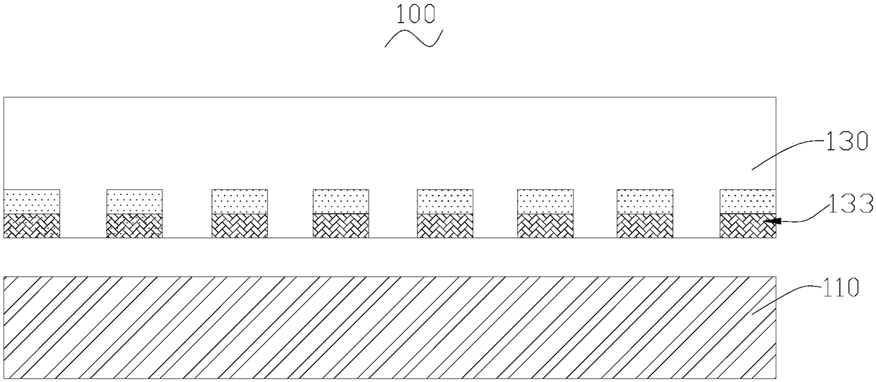
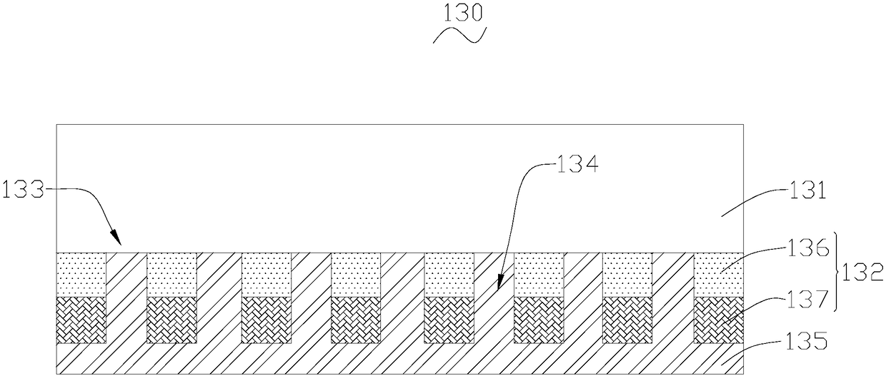
[0030] Please also see figure 1 and figure 2 , the 3D display device 100 includes a display 110 and a glass cover assembly 130 , and the glass cover assembly 130 is disposed on the light emitting side of the display 110 . Optionally, the 3D display device 100 may be a device with display and touch screen functions such as a mobile phone, a tablet, a vehicle-mounted computer, a vehicle-mounted display, or a computer, which is not limited in the present invent...


PUM


Abstract

The invention provides a glass cover plate component. The glass cover plate component comprises a glass cover plate and a slit grating pattern layer. The slit grating pattern layer is arranged in theinner surface of the glass cover plate. The slit grating pattern layer comprises a plurality of slit grating units. Each two of the plurality of slit grating units are oppositely arranged in the innersurface of the glass cover plate at intervals and the plurality of slits which are uniformly distributed are formed so as to form a slit grating pattern. The invention also provides the 3D display device using the glass cover plate component and the manufacturing method of the glass cover plate component.

Description

technical field [0001] The invention relates to the technical field of stereoscopic display, in particular to a glass cover assembly, a 3D display device and a preparation method. Background technique [0002] At present, there are a variety of naked-eye 3D products on the market, such as mobile phones / tablets with liquid crystal slit gratings, mobile phones / tablets with cylindrical lens films, and mobile phones / tablets with liquid crystal lenses. These products all need to add 3D optical devices on the basis of the original 2D products, such as liquid crystal slit gratings, lens films, and liquid crystal lenses. Adding these devices will undoubtedly increase the thickness and weight of the product, which is very important for portable handheld terminals. disadvantage. Moreover, with the development of touch technology, in cell technology has become the standard configuration of flagship models of various brands, which shows that in cell technology will inevitably become a ...

Claims


Application Information

Patent Timeline
Patent Type & Authority Applications(China)
IPC IPC(8): G02B27/22G02B30/30
CPCG02B30/30G02B5/18
Inventor 贺曙刘晓林
Owner FUTURE TECH XIANG YANG CO LTD
Learn More