
A common-aperture composite optical system for visible light and mid-wave infrared

An optical system and visible light technology, applied in the optical field, can solve problems such as difficulty in meeting wide-area reconnaissance requirements, difficulty in system installation and adjustment, and small field of view of the system, achieving image fusion, reducing installation and adjustment difficulty, and compact structure. Effect

Active Publication Date: 2020-07-17
BEIJING HUAHANG RADIO MEASUREMENT & RES INST
View PDF22 Cites 0 Cited by
  • Summary
  • Abstract
  • Description
  • Claims
  • Application Information

AI Technical Summary

Problems solved by technology

After investigation, most of the current dual-band common-aperture optical systems adopt the catadioptric structure, which has the advantage of being conducive to the integration of visible light and infrared bands, but the disadvantage is that the system has a small field of view and is difficult to install and adjust.
For example, "Applied Optics" reported in the fourth issue of 2010 that Cai Zhanen and others designed a large field of view and large relative aperture dual-band R-C optical system. The field of view is only ±2.5°, which is difficult to meet the needs of wide-area reconnaissance. At the same time, due to the catadioptric structure, the system is difficult to install and adjust, and the reliability is not high

Method used


Image

  • A common-aperture composite optical system for visible light and mid-wave infrared
  • A common-aperture composite optical system for visible light and mid-wave infrared
  • A common-aperture composite optical system for visible light and mid-wave infrared

Examples


Embodiment Construction

[0038] Preferred embodiments of the present invention will be specifically described below in conjunction with the accompanying drawings, wherein the accompanying drawings constitute a part of the application and are used together with the embodiments of the present invention to explain the principles of the present invention.

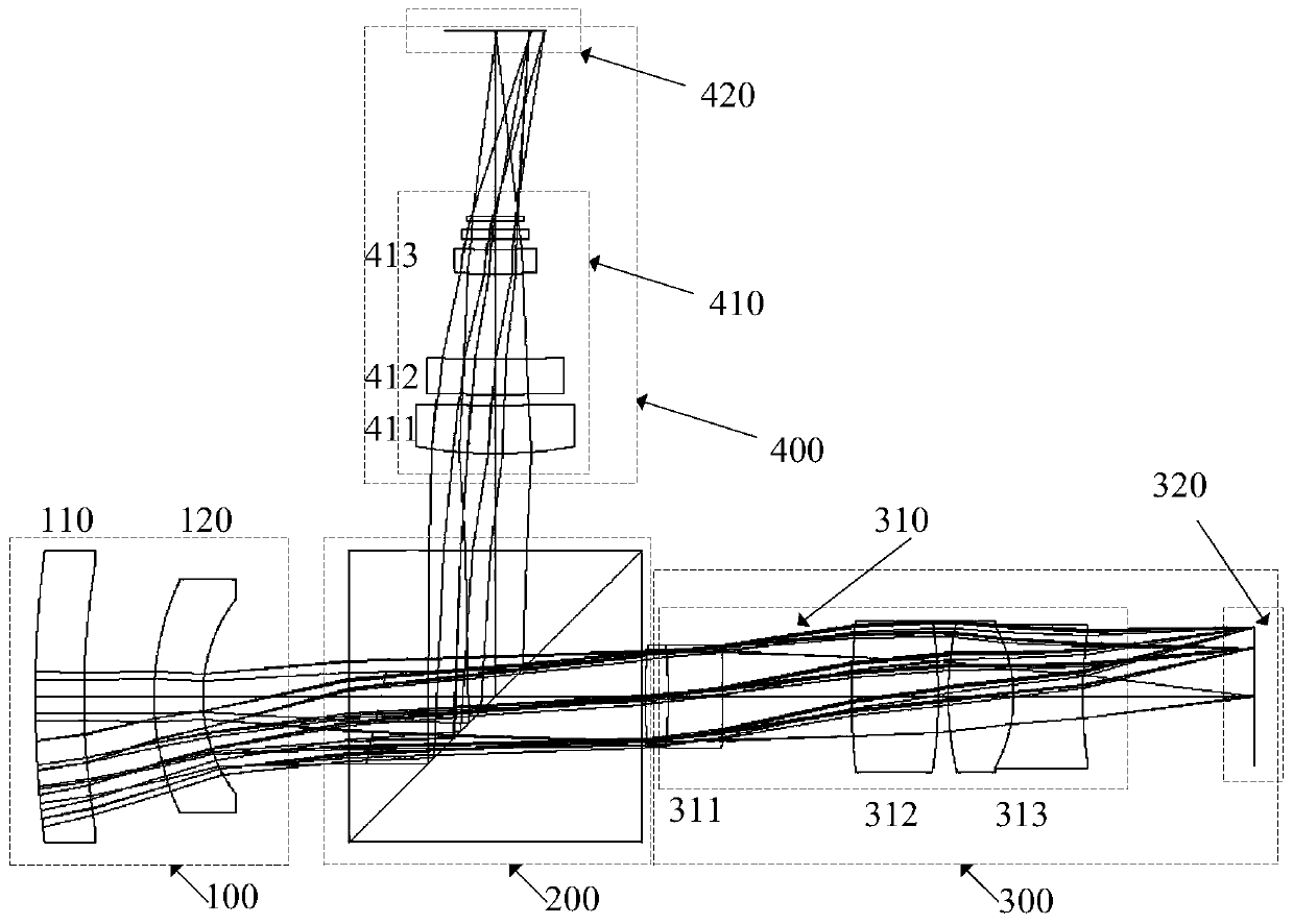
[0039] A specific embodiment of the present invention discloses a common-aperture composite optical system for visible light and mid-wave infrared, which is an optical system suitable for wide-area day and night reconnaissance, such as figure 1 As shown, it consists of four parts: a common transmission system (100), a beam splitting prism group (200), a visible light path correction system (300) and an infrared light path correction system (400);

[0040] The shared transmission system (100) is composed of a transmission lens 1 (110) and a transmission lens 2 (120) along the optical path direction, both lenses are negative power lenses, and the lens mat...


PUM

PropertyMeasurementUnit
refractive indexaaaaaaaaaa

Abstract

The invention discloses a visible light and medium wave infrared common-caliber composite optical system. The system comprises four parts, namely a common transmission system (100), a beam splitter prism group (200), a visible light path correcting system (300) and an infrared light path correcting system (400). The system covers two wave bands of the visible wave band and the medium wave infraredband, and can work in the daytime and at night respectively. Therefore, the imaging at a large view field and all day long can be realized. Compared with a traditional split structure, the system hasthe advantages of compact structure, good co-axial consistency, high pointing precision, small volume and light weight. Compared with a novel common-caliber folding and reflecting structure, the system has the advantages of large visual field, easy and convenient installation and adjustment, and the like. The system can realize the wide-area and all-day-time monitoring effect for a target area, and the performance of photoelectric reconnaissance equipment is effectively improved.

Description

technical field [0001] The invention belongs to the field of optical technology, and relates to a visible light and mid-wave infrared co-aperture composite optical system. Background technique [0002] At present, the smart airborne pod has attracted much attention in the aviation field because of its advantages of flexibility and convenience. By investigating the research status of airborne pods at home and abroad, it can be seen that the development momentum of smart aviation airborne pods is strong, and they are constantly pursuing wide coverage, long-distance and all-weather imaging. At the same time, the reduction of volume and weight means the increase of flight speed and distance. Therefore, under the premise of satisfying the imaging quality, the optical system with small size and compact structure has become a research hotspot. [0003] At present, the smart airborne pod developed by our country has a single imaging band and a narrow coverage of reconnaissance imag...

Claims


Application Information

Patent Timeline
Patent Type & Authority Patents(China)
IPC IPC(8): G02B27/10G02B27/00
CPCG02B27/0025G02B27/1006
Inventor 王敬洋于云翔廉黎朱亮樊立
Owner BEIJING HUAHANG RADIO MEASUREMENT & RES INST
Learn More