
Pipeline, pipeline system and air conditioner

A pipeline system and pipeline technology, applied in mechanical equipment, fluid circulation arrangements, refrigeration components, etc., can solve the problems of increasing the complexity of the piping structure, reducing the efficiency of air conditioning and refrigeration, and small impact resistance, and achieving the pipeline structure and Parameter optimization, improving shock absorption, reducing production costs

Active Publication Date: 2018-06-12
AUX AIR CONDITIONING LTD BY SHARE LTD
View PDF10 Cites 1 Cited by
  • Summary
  • Abstract
  • Description
  • Claims
  • Application Information

AI Technical Summary

Problems solved by technology

At present, due to the large number of components such as compressors, oil components, gas components, and liquid storage tanks in commercial air conditioners, the piping system is very complicated, the production efficiency is low, and damage problems occur from time to time. The most common failures in the process come from piping
[0003] In addition, during the transportation, installation and start-up of the air conditioner, there are usually various vibrations and shocks. The existing air-conditioning pipeline system is often prone to fatigue and fracture due to poor shock absorption and low impact resistance. performance failure, resulting in huge economic losses and affecting normal use
[0004] In order to reduce the vibration and noise when the air conditioner is working, and reduce the risk of pipe breakage, the existing suction pipes and exhaust pipes often use multiple U-shaped bends, as well as mufflers, shock absorbers and damping blocks. However, such a design will usually further increase the complexity of the piping structure, cause serious consumption of raw materials, high product costs, and weaken the market competitiveness of the product; moreover, multiple bends will increase the length of the piping and reduce the cooling efficiency of the air conditioner

Method used


Image

  • Pipeline, pipeline system and air conditioner
  • Pipeline, pipeline system and air conditioner
  • Pipeline, pipeline system and air conditioner

Examples


Embodiment Construction

[0035] It should be noted that, in the case of no conflict, the embodiments of the present invention and the features in the embodiments can be combined with each other.

[0036] The present invention will be described in detail below with reference to the accompanying drawings and examples.

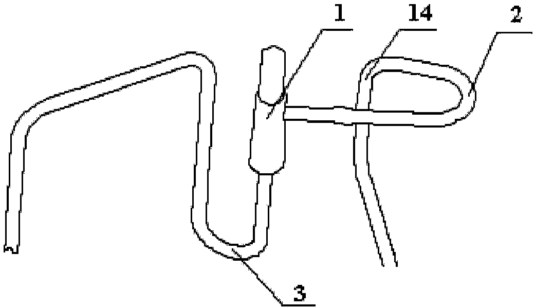
[0037] Please refer to figure 1 As shown, the present invention provides a pipeline, including a solenoid valve 1 , a first U-shaped elbow 2 connected to the solenoid valve 1 , and a second U-shaped elbow 3 connected to the solenoid valve 1 .

[0038] Wherein, the plane where the first U-shaped elbow 2 is located and the horizontal plane form a first included angle α1, 0°≤α1<90°, and the plane where the second U-shaped elbow 3 is located and the horizontal plane form a second angle α1. The angle is α2, 30°≤α2≤90°, and α1≠α2.

[0039] Preferably, the first included angle α1=0°, the second included angle is α2=90°, that is, the first U-shaped bend 2 is a horizontal U-shaped bend, and the...


PUM


Abstract

The invention provides a pipeline, a pipeline system and an air conditioner. The pipeline comprises an electromagnetic valve, a first U-shaped bend connected with the electromagnetic valve, and a second U-shaped bend connected with the electromagnetic valve. The plane where the first U-shaped bend is located and the horizontal plane form a first included angle alpha 1 which is not smaller than 0 degree and smaller than 90 degrees. The plane where the second U-shaped bend is located and the horizontal plane form a second included angle alpha 2 which is not smaller than 30 degrees and smaller than or equal to 90 degrees, and alpha 1 is not equal to alpha 2. According to the pipeline, the pipeline system and the air conditioner, the structure is simple, the cost is low, assembling is convenient, the damping effect is good, the reliability is high, and production efficiency is improved.

Description

technical field [0001] The invention relates to the technical field of air conditioning, in particular to a pipeline, a pipeline system and an air conditioner. Background technique [0002] In the field of air conditioning technology, the pipeline system is one of the most critical components of the air conditioner. At present, due to the large number of components such as compressors, oil separators, gas separators, and liquid storage tanks in commercial air conditioners, the piping system is very complicated, the production efficiency is low, and damage problems occur from time to time. The most common failures in the process come from piping. [0003] In addition, during the transportation, installation and start-up of the air conditioner, there are usually various vibrations and shocks. The existing air conditioning pipeline system is often prone to fatigue and fracture due to poor shock absorption and low impact resistance, which in turn makes the air conditioner The ...

Claims


Application Information

Patent Timeline
Patent Type & Authority Applications(China)
IPC IPC(8): F25B41/04F25B41/20
CPCF25B41/20
Inventor 兰江华
Owner AUX AIR CONDITIONING LTD BY SHARE LTD
Learn More