
Positioning transferring device and technology for lighter automatic stacking machine

A technology for lighters and stackers, which is applied in packaging, transportation and packaging, and individual objects, and can solve problems such as failure to meet the yield rate, safety of explosive personnel, and danger

Active Publication Date: 2018-06-12
邵东县莲花打火机制造有限公司
View PDF5 Cites 5 Cited by
  • Summary
  • Abstract
  • Description
  • Claims
  • Application Information

AI Technical Summary

Problems solved by technology

In recent years, the industry has continuously improved and perfected the structure of many parts of lighters to improve the quality of lighters and meet people's pursuit of lighter performance and exquisite grades. However, due to the increasing demand for lighters in the market, , so lighters are mass-produced. Now lighter assembly machines are widely used. Stacking assembled lighters requires a lot of manpower. Generally, a lighter assembly machine needs to be equipped with 3-5 workers to be responsible for stacking. However, existing The labor cost is high, and the probability of human misplacement is as high as 5%-8%, and the yield rate cannot meet the standard, which will affect the subsequent labeling, silk screen printing, packaging and other processes
[0003] Nowadays, the transfer of assembled lighters is mostly done by manually inserting lighters into jigs. Lighters are dangerous products, which are prone to explosion and pose a danger to personnel safety, and workers need to work uninterrupted, which is labor-intensive; In time, the lighter will accumulate during the transfer process, causing the surface of the lighter shell to be bumped and scratched, resulting in defective lighters

Method used


Image

  • Positioning transferring device and technology for lighter automatic stacking machine
  • Positioning transferring device and technology for lighter automatic stacking machine
  • Positioning transferring device and technology for lighter automatic stacking machine

Examples


Embodiment 1

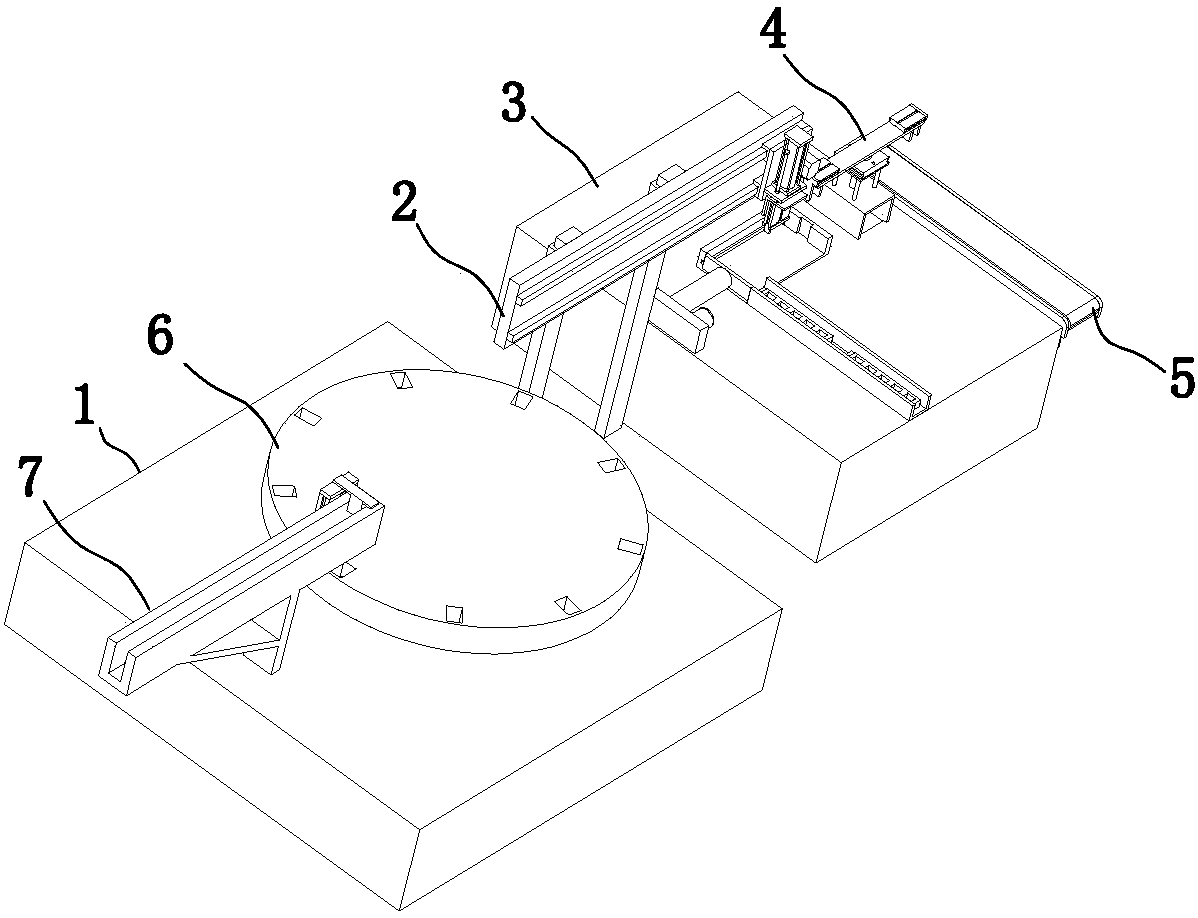
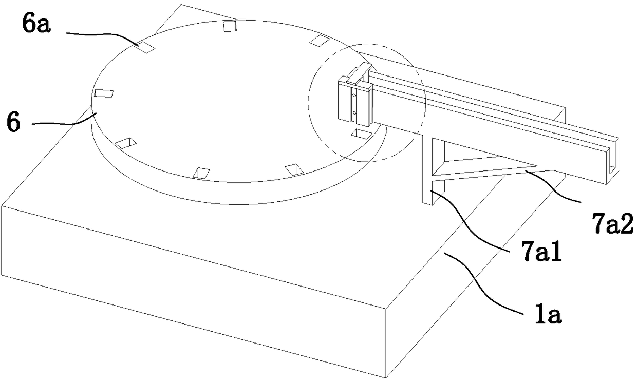
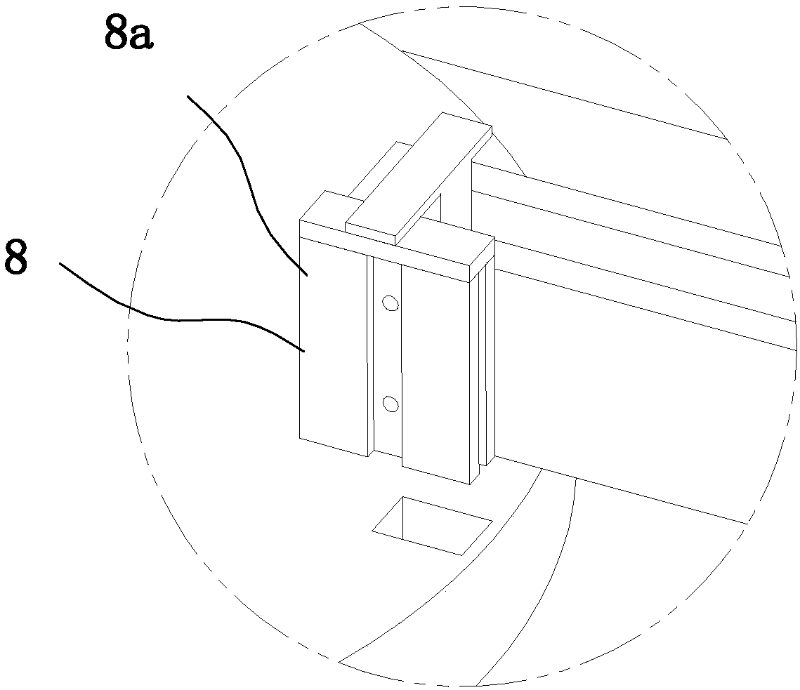
[0037] refer to Figure 1 to Figure 11 The shown lighter automatic stacking machine includes a feeding platform 1, a positioning shifting device 2, a supporting platform 3 and a feeding device 4, and the positioning shifting device 2 is located on the side of the feeding platform 1 and is adjacent to the top of the feeding platform 1. Cooperate, the supporting platform 3 is positioned at the side of the positioning shifting device 2 away from the feeding platform 1, and the unloading device 4 is positioned at the top of the supporting platform 3 and cooperates with the positioning shifting device 2, and the side of the supporting platform 3 is provided with The unloading conveyor belt 5, the unloading conveyor belt 5 cooperates with the unloading device 4 on the support platform 3, the top of the feeding platform 1 is provided with a turntable 6 that matches the positioning and shifting device 2 and directly above the turntable 6 The first conveyor belt 7 for transporting the ...

Embodiment 2

[0055] Please refer to the attached Figure 1-11 , the positioning and shifting process of the positioning and shifting device of the above-mentioned lighter automatic stacking machine includes the following steps:

[0056] S1. The positioning fixture 2e1 is conveyed by the second conveyor belt 2e3, and the positioning block 2e4 is located directly in front of the output end of the second conveyor belt 2e3;

[0057] S2. The translation assembly 2b slides to the specified position on the support assembly 2a, the lifting assembly 2c drives the air clamp 2d to move vertically downward to clamp the lighter on the turntable 6, the lifting assembly 2c drives the air clamp 2d to move vertically upwards and then translates the assembly 2b Move to just above the positioning jig 2e1;

[0058] S3. The lifting component 2c drives the air clamp 2d to move vertically downward, and the air clamp 2d inserts the lighter into the positioning fixture 2e1 of the positioning member 2e;

[0059] ...


PUM


Abstract

The invention relates to the field of lighter production, in particular to a positioning transferring device for a lighter automatic stacking machine. The positioning transferring device is arranged on a bearing platform and comprises a supporting assembly, a translation assembly, a lifting assembly and a gas clamp. The translation assembly is located on the upper section of the supporting assembly and slidably matched with the supporting assembly, and the lifting assembly is located by the side of the translation assembly and fixedly connected with the translation assembly. The gas clamp is located under the lifting assembly and fixedly connected with the lifting assembly. The positioning transferring device further comprises a positioning piece located at the top of the bearing platform,and the positioning piece comprises a positioning jig, a pushing piece, a positioning block and a second conveyor belt for conveying the positioning jig. The positioning jig is located on the secondconveyor belt, and the pushing piece is located by the side of the output end of the second conveyor belt. The positioning block is located in front of the output end of the second conveyor belt. According to the positioning transferring device, lighters are transferred into inserting grooves of the positioning jig one by one through the gas clamp, the accuracy rate reaches 99.9% or above, the technology is simple and reliable, and the efficiency is 8-10 times or above of the manual efficiency.

Description

technical field [0001] The invention relates to the field of lighter production, in particular to a positioning material-moving device and a positioning material-moving process of an automatic lighter stacking machine. Background technique [0002] Lighter is a commonly used device for making fire in people's daily life, and it is also often chosen as a courtesy gift in business and interpersonal communication. In recent years, the industry has continuously improved and perfected the structure of many parts of lighters to improve the quality of lighters and meet people's pursuit of lighter performance and exquisite grades. However, due to the increasing demand for lighters in the market, , so lighters are mass-produced. Now lighter assembly machines are widely used. Stacking assembled lighters requires a lot of manpower. Generally, a lighter assembly machine needs to be equipped with 3-5 workers to be responsible for stacking. However, existing The labor cost is high, and t...

Claims


Application Information

Patent Timeline
IPC IPC(8): B65B5/10B65B43/42B65B35/18
CPCB65B5/105B65B35/18B65B43/42
Inventor 曾国强
Owner 邵东县莲花打火机制造有限公司
Learn More